Three Port 10/100 Managed Ethernet Switch with MII
Datasheet
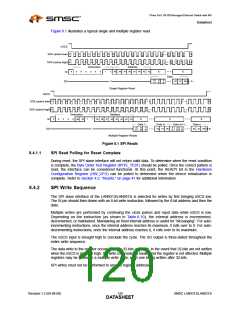
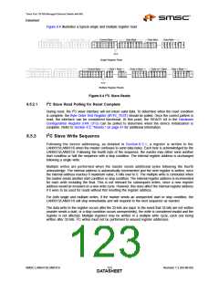
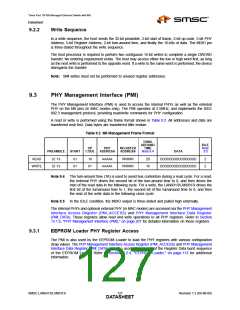
Figure 8.4 illustrates a typical single and multiple register read.
Control Byte
Control Byte
Address Byte
Data Byte
Data Byte... ...Data Byte
S
A
6
S
A
5
S
A
4
S
A
3
S
A
2
S
A
1
S
A
0
A
C
K
A
C
K
S
A
6
S
A
5
S
A
4
S
A
3
S
A
2
S
A
1
S
A
0
A
C
K
D
3
1
D
3
0
D
2
9
D
2
8
S
2
7
D
2
6
D
2
5
D
2
4
A
C
K
D
2
3
D
2
2
D
2
1
D
A
C
K
A
9
A
8
A
7
A
6
A
5
A
4
A
3
A
2
D
5
D
4
D
3
D
2
D
1
D
0
2 ...
S
0
S
1
P
0
R/~W
Single Register Read
Control Byte
Control Byte
Address Byte
Data 1 Byte
...Data m Byte
3 ... 2 ...
Data m+1 Byte.........Data n Byte
S
A
6
S
A
5
S
A
4
S
A
3
S
A
2
S
A
1
S
A
0
A
C
K
A
C
K
S
A
6
S
A
5
S
A
4
S
A
3
S
A
2
S
A
1
S
A
0
A
C
K
D
3
1
D
D
D
2
4
A
C
K
A
C
K
D
3
1
D
3
0
D
2
9
D
2
8
D
2
7
D
2
6
A
C
K
A
9
A
8
A
7
A
6
A
5
A
4
A
3
A
2
D
4
D
3
D
2
D
1
D
0
D
4
D
3
D
2
D
1
D
0
S
0
S
1
P
0
5
R/~W
Multiple Register Reads
Figure 8.4 I2C Slave Reads
2
8.5.2.1
I C Slave Read Polling for Reset Complete
2
During reset, the I C slave interface will not return valid data. To determine when the reset condition
is complete, the Byte Order Test Register (BYTE_TEST) should be polled. Once the correct pattern is
read, the interface can be considered functional. At this point, the READY bit in the Hardware
Configuration Register (HW_CFG) can be polled to determine when the device initialization is
complete. Refer to Section 4.2, "Resets," on page 41 for additional information.
2
8.5.3
I C Slave Write Sequence
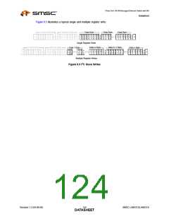
Following the device addressing, as detailed in Section 8.5.1, a register is written to the
LAN9313/LAN9313i when the master continues to send data bytes. Each byte is acknowledged by the
LAN9313/LAN9313i. Following the fourth byte of the sequence, the master may either send another
start condition or halt the sequence with a stop condition. The internal register address is unchanged
following a single write.
Multiple writes are performed when the master sends additional bytes following the fourth
acknowledge. The internal address is automatically incremented and the next register is written. once
the internal address reaches it maximum value, it rolls over to 0. The multiple write is concluded when
the master sends another start condition or stop condition. The internal register address is incremented
for each write including the final. This is not relevant for subsequent writes, since a new register
address would be included on a new write cycle. However, this does affect the internal register address
if it were to be used for reads without first resetting the register address.
For both single and multiple writes, if the master sends an unexpected start or stop condition, the
LAN9313/LAN9313i will stop immediately and will respond to the next sequence as needed.
The data write to the register occurs after the 32-bits are input. In the event that 32-bits are not written
(master sends a start, or a stop condition occurs unexpectedly), the write is considered invalid and the
register is not affected. Multiple registers may be written in a multiple write cycle, each one being
2
written after 32-bits. I C writes must not be performed to unused register addresses.
SMSC LAN9313/LAN9313i
123
Revision 1.2 (04-08-08)
DATASHEET

 SMSC [ SMSC CORPORATION ]