Three Port 10/100 Managed Ethernet Switch with MII
Datasheet
8.2.4
EEPROM Loader
2
The EEPROM Loader interfaces to the I C/Microwire EEPROM controller, the PHYs, and to the system
CSRs (via the Register Access MUX). All system CSRs are accessible to the EEPROM Loader.
The EEPROM Loader runs upon a pin reset (nRST), power-on reset (POR), digital reset
(DIGITAL_RST bit in the Reset Control Register (RESET_CTL)), or upon the issuance of a RELOAD
command via the EEPROM Command Register (E2P_CMD). Refer to Section 4.2, "Resets," on
page 41 for additional information on the LAN9313/LAN9313i resets.
The EEPROM contents must be loaded in a specific format for use with the EEPROM Loader. An
overview of the EEPROM content format is shown in Table 8.7. Each section of EEPROM contents is
discussed in detail in the following sections.
Table 8.7 EEPROM Contents Format Overview
EEPROM ADDRESS
DESCRIPTION
EEPROM Valid Flag
VALUE
0
A5h
st
1
MAC Address Low Word [7:0]
MAC Address Low Word [15:8]
MAC Address Low Word [23:16]
MAC Address Low Word [31:24]
MAC Address High Word [7:0]
MAC Address High Word [15:8]
Configuration Strap Values Valid Flag
Configuration Strap Values
1
Byte on the Network
Byte on the Network
Byte on the Network
Byte on the Network
Byte on the Network
Byte on the Network
A5h
nd
rd
2
2
3
4
3
4
5
6
th
th
th
5
6
7
8 - 11
12
13
See Table 8.8
Burst Sequence Valid Flag
A5h
Number of Bursts
See Section 8.2.4.5,
"Register Data"
14 and above
Burst Data
See Section 8.2.4.5,
"Register Data"
8.2.4.1
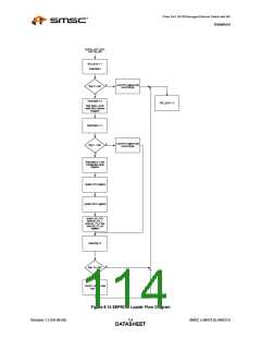
EEPROM Loader Operation
Upon a pin reset (nRST), power-on reset (POR), digital reset (DIGITAL_RST bit in the Reset Control
Register (RESET_CTL)), or upon the issuance of a RELOAD command via the EEPROM Command
Register (E2P_CMD), the EPC_BUSY bit in the EEPROM Command Register (E2P_CMD) will be set.
While the EEPROM Loader is active, the READY bit of the Hardware Configuration Register
(HW_CFG) is cleared and no writes to the LAN9313/LAN9313i should be attempted. The operational
flow of the EEPROM Loader can be seen in Figure 8.14.
SMSC LAN9313/LAN9313i
113
Revision 1.2 (04-08-08)
DATASHEET

 SMSC [ SMSC CORPORATION ]