Three Port 10/100 Managed Ethernet Switch with MII
Datasheet
Note: Each of these PHY registers is written in its entirety, overwriting any previously changed bits.
8.2.4.4.2
VIRTUAL PHY REGISTERS SYNCHRONIZATION
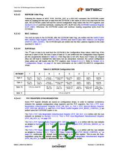
Some PHY register defaults are based on configuration straps. In order to maintain consistency
between the updated configuration strap registers and the Virtual PHY registers, the Virtual PHY Auto-
Negotiation Advertisement Register (VPHY_AN_ADV), Virtual PHY Special Control/Status Register
(VPHY_SPECIAL_CONTROL_STATUS), and Virtual PHY Basic Control Register
(VPHY_BASIC_CTRL) are written when the EEPROM Loader is run.
The Virtual PHY Auto-Negotiation Advertisement Register (VPHY_AN_ADV) is written with the new
defaults as detailed in Section 13.1.7.5, "Virtual PHY Auto-Negotiation Advertisement Register
(VPHY_AN_ADV)," on page 216.
The Virtual PHY Special Control/Status Register (VPHY_SPECIAL_CONTROL_STATUS) is written
with the new defaults as detailed in Section 13.1.7.8, "Virtual PHY Special Control/Status Register
(VPHY_SPECIAL_CONTROL_STATUS)," on page 222.
The Virtual PHY Basic Control Register (VPHY_BASIC_CTRL) is written with the new defaults as
detailed in Section 13.1.7.1, "Virtual PHY Basic Control Register (VPHY_BASIC_CTRL)," on page 210.
Additionally, the Restart Auto-negotiation bit is set in this register. This re-runs the Auto-negotiation
using the new default values of the Virtual PHY Auto-Negotiation Advertisement Register
(VPHY_AN_ADV) register to determine the new Auto-negotiation results.
Note: Each of these VPHY registers is written in its entirety, overwriting any previously changed bits.
8.2.4.4.3
8.2.4.5
LED AND MANUAL FLOW CONTROL REGISTER SYNCHRONIZATION
Since the defaults of the LED Configuration Register (LED_CFG), Port 1 Manual Flow Control Register
(MANUAL_FC_1), Port 2 Manual Flow Control Register (MANUAL_FC_2), and Port 0(External MII)
Manual Flow Control Register (MANUAL_FC_MII) are based on configuration straps, the EEPROM
Loader reloads these registers with their new default values.
Register Data
Optionally following the configuration strap values, the EEPROM data may be formatted to allow
access to the LAN9313/LAN9313i parallel, directly writable registers. Access to indirectly accessible
registers (e.g. Switch Engine registers, etc.) is achievable with an appropriate sequence of writes (at
the cost of EEPROM space).
This data is first preceded with a Burst Sequence Valid Flag (EEPROM byte 12). If this byte has a
value of A5h, the data that follows is recognized as a sequence of bursts. Otherwise, the EEPROM
Loader is finished, will go into a wait state, and clear the EPC_BUSY bit in the EEPROM Command
Register (E2P_CMD). This can optionally generate an interrupt.
The data at EEPROM byte 13 and above should be formatted in a sequence of bursts. The first byte
is the total number of bursts. Following this is a series of bursts, each consisting of a starting address,
count, and the count x 4 bytes of data. This results in the following formula for formatting register data:
8-bits number_of_bursts
repeat (number_of_bursts)
16-bits {starting_address[9:2] / count[7:0]}
repeat (count)
8-bits data[31:24], 8-bits data[23:16], 8-bits data[15:8], 8-bits data[7:0]
Note: The starting address is a DWORD address. Appending two 0 bits will form the register address.
Revision 1.2 (04-08-08)
116
SMSC LAN9313/LAN9313i
DATASHEET

 SMSC [ SMSC CORPORATION ]