Small Footprint MII/RMII 10/100 Ethernet Transceiver for Automotive Applications
Datasheet
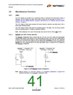
3.8.1.2
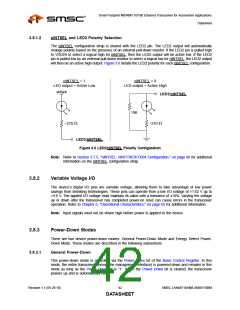
nINTSEL and LED2 Polarity Selection
The nINTSEL configuration strap is shared with the LED2 pin. The LED2 output will automatically
change polarity based on the presence of an external pull-down resistor. If the LED2 pin is pulled high
to VDD2A to select a logical high for nINTSEL, then the LED2 output will be active low. If the LED2
pin is pulled low by an external pull-down resistor to select a logical low for nINTSEL, the LED2 output
will then be an active high output. Figure 3.6 details the LED2 polarity for each nINTSEL configuration.
nINTSEL = 1
nINTSEL = 0
LED output = Active Low
LED output = Active High
VDD2A
LED2/nINTSEL
10K
~270 Ω
~270 Ω
LED2/nINTSEL
Figure 3.6 LED2/nINTSEL Polarity Configuration
Note: Refer to Section 3.7.5, "nINTSEL: nINT/TXER/TXD4 Configuration," on page 40 for additional
information on the nINTSEL configuration strap.
3.8.2
Variable Voltage I/O
The device’s digital I/O pins are variable voltage, allowing them to take advantage of low power
savings from shrinking technologies. These pins can operate from a low I/O voltage of +1.62 V up to
+3.6 V. The applied I/O voltage must maintain its value with a tolerance of ±10%. Varying the voltage
up or down after the transceiver has completed power-on reset can cause errors in the transceiver
operation. Refer to Chapter 5, "Operational Characteristics," on page 65 for additional information.
Note: Input signals must not be driven high before power is applied to the device.
3.8.3
Power-Down Modes
There are two device power-down modes: General Power-Down Mode and Energy Detect Power-
Down Mode. These modes are described in the following subsections.
3.8.3.1
General Power-Down
This power-down mode is controlled via the Power Down bit of the Basic Control Register. In this
mode, the entire transceiver (except the management interface) is powered-down and remains in this
mode as long as the Power Down bit is “1”. When the Power Down bit is cleared, the transceiver
powers up and is automatically reset.
Revision 1.1 (05-26-10)
42
SMSC LAN88710AM/LAN88710BM
DATASHEET

 SMSC [ SMSC CORPORATION ]