Small Footprint MII/RMII 10/100 Ethernet Transceiver for Automotive Applications
Datasheet
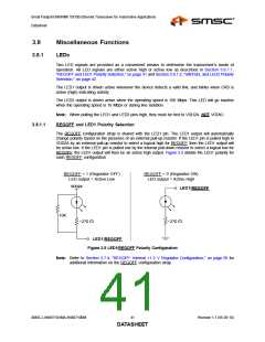
3.8.9
Loopback Operation
The device may be configured for near-end loopback and far loopback. These loopback modes are
detailed in the following subsections.
3.8.9.1
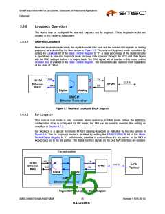
Near-end Loopback
Near-end loopback mode sends the digital transmit data back out the receive data signals for testing
purposes, as indicated by the blue arrows in Figure 3.7. The near-end loopback mode is enabled by
setting the Loopback bit of the Basic Control Register to “1”. A large percentage of the digital circuitry
is operational in near-end loopback mode because data is routed through the PCS and PMA layers
into the PMD sublayer before it is looped back. The COL signal will be inactive in this mode, unless
Collision Test is enabled in the Basic Control Register. The transmitters are powered down regardless
of the state of TXEN.
TXD
RXD
TX
RX
10/100
Ethernet
MAC
X
X
CAT-5
XFMR
Digital
Analog
SMSC
Ethernet Transceiver
Figure 3.7 Near-end Loopback Block Diagram
3.8.9.2
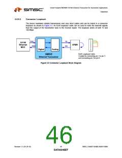
Far Loopback
This special test mode is only available when operating in RMII mode. When the RMIISEL
configuration strap is configured for MII mode, the SMI can be used to override this setting as
described in Section 3.7.3.
Far loopback is a special test mode for MDI (analog) loopback as indicated by the blue arrows in
Figure 3.8. The far loopback mode is enabled by setting the FARLOOPBACK bit of the Mode
Control/Status Register to “1”. In this mode, data that is received from the link partner on the MDI is
looped back out to the link partner. The digital interface signals on the local MAC interface are isolated.
Far-end system
TXD
TX
RX
10/100
Ethernet
MAC
X
Link
Partner
CAT-5
XFMR
RXDX
Digital
Analog
SMSC
Ethernet Transceiver
Figure 3.8 Far Loopback Block Diagram
SMSC LAN88710AM/LAN88710BM
45
Revision 1.1 (05-26-10)
DATASHEET

 SMSC [ SMSC CORPORATION ]