Small Footprint MII/RMII 10/100 Ethernet Transceiver for Automotive Applications
Datasheet
3.7.2
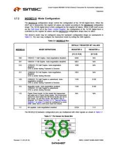
MODE[2:0]: Mode Configuration
The MODE[2:0] configuration straps control the configuration of the 10/100 digital block. When the
nRST pin is deasserted, the register bit values are loaded according to the MODE[2:0] configuration
straps. The 10/100 digital block is then configured by the register bit values. When a soft reset occurs
via the Soft Reset bit of the Basic Control Register, the configuration of the 10/100 digital block is
controlled by the register bit values and the MODE[2:0] configuration straps have no affect.
The device’s mode may be configured using the hardware configuration straps as summarized in
Table 3.6. The user may configure the transceiver mode by writing the SMI registers.
Table 3.6 MODE[2:0] Bus
DEFAULT REGISTER BIT VALUES
MODE[2:0]
MODE DEFINITIONS
REGISTER 0
[13,12,10,8]
REGISTER 4
[8,7,6,5]
000
001
010
10BASE-T Half Duplex. Auto-negotiation disabled.
10BASE-T Full Duplex. Auto-negotiation disabled.
0000
0001
1000
N/A
N/A
N/A
100BASE-TX Half Duplex. Auto-negotiation
disabled.
CRS is active during Transmit & Receive.
011
100
101
110
100BASE-TX Full Duplex. Auto-negotiation
disabled.
1001
1100
1100
N/A
N/A
0100
0100
N/A
CRS is active during Receive.
100BASE-TX Half Duplex is advertised. Auto-
negotiation enabled.
CRS is active during Transmit & Receive.
Repeater mode. Auto-negotiation enabled.
100BASE-TX Half Duplex is advertised.
CRS is active during Receive.
Power-Down mode. In this mode the transceiver
will wake-up in Power-Down mode. The transceiver
cannot be used when the MODE[2:0] bits are set to
this mode. To exit this mode, the MODE bits in
Register 18.7:5(see Section 4.2.9, "Special Modes
Register," on page 61) must be configured to some
other value and a soft reset must be issued.
111
All capable. Auto-negotiation enabled.
X10X
1111
The MODE[2:0] hardware configuration pins are multiplexed with other signals as shown in Table 3.7.
Table 3.7 Pin Names for Mode Bits
MODE BIT
PIN NAME
MODE[0]
MODE[1]
MODE[2]
RXD0/MODE0
RXD1/MODE1
COL/CRS_DV/MODE2
Revision 1.1 (05-26-10)
38
SMSC LAN88710AM/LAN88710BM
DATASHEET

 SMSC [ SMSC CORPORATION ]