Small Footprint MII/RMII 10/100 Ethernet Transceiver for Automotive Applications
Datasheet
3.8
Miscellaneous Functions
3.8.1
LEDs
Two LED signals are provided as a convenient means to determine the transceiver's mode of
operation. All LED signals are either active high or active low as described in Section 3.8.1.1,
"REGOFF and LED1 Polarity Selection," on page 41 and Section 3.8.1.2, "nINTSEL and LED2 Polarity
Selection," on page 42.
The LED1 output is driven active whenever the device detects a valid link, and blinks when CRS is
active (high) indicating activity.
The LED2 output is driven active when the operating speed is 100 Mbps. This LED will go inactive
when the operating speed is 10 Mbps or during line isolation.
Note: When pulling the LED1 and LED2 pins high, they must be tied to VDD2A, NOT VDDIO.
3.8.1.1
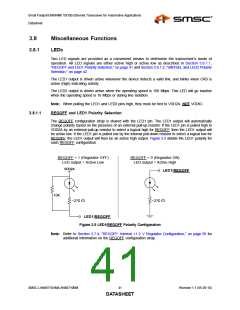
REGOFF and LED1 Polarity Selection
The REGOFF configuration strap is shared with the LED1 pin. The LED1 output will automatically
change polarity based on the presence of an external pull-up resistor. If the LED1 pin is pulled high to
VDD2A by an external pull-up resistor to select a logical high for REGOFF, then the LED1 output will
be active low. If the LED1 pin is pulled low by the internal pull-down resistor to select a logical low for
REGOFF, the LED1 output will then be an active high output. Figure 3.5 details the LED1 polarity for
each REGOFF configuration.
REGOFF = 1 (Regulator OFF)
LED output = Active Low
REGOFF = 0 (Regulator ON)
LED output = Active High
VDD2A
LED1/REGOFF
10K
~270 Ω
~270 Ω
LED1/REGOFF
Figure 3.5 LED1/REGOFF Polarity Configuration
Note: Refer to Section 3.7.4, "REGOFF: Internal +1.2 V Regulator Configuration," on page 39 for
additional information on the REGOFF configuration strap.
SMSC LAN88710AM/LAN88710BM
41
Revision 1.1 (05-26-10)
DATASHEET

 SMSC [ SMSC CORPORATION ]