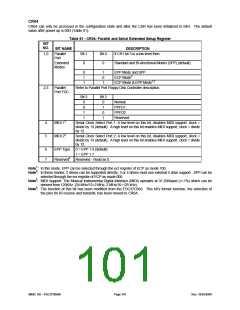
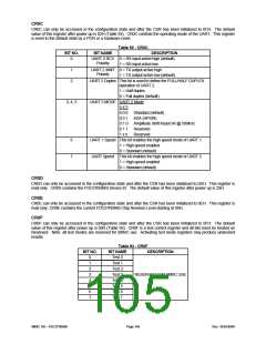
CR04
CR04 can only be accessed in the configuration state and after the CSR has been initialized to 04H. The default
value after power up is 00H (Table 81).
Table 81 - CR04: Parallel and Serial Extended Setup Register
BIT
NO.
BIT NAME
DESCRIPTION
1,0
Parallel
Bit 1
0
Bit 0
0
If CR1 bit 3 is a low level then:
Port
Extended
Modes
Standard and Bi-directional Modes (SPP) (default)
0
1
1
1
0
1
EPP Mode and SPP
ECP Mode2
ECP Mode & EPP Mode1,2
2,3
Parallel
Refer to Parallel Port Floppy Disk Controller description.
Port FDC
Bit 3
Bit 2
0
0
1
1
0
1
0
1
Normal
PPFD1
PPFD2
Reserved
4
5
MIDI 13
Serial Clock Select Port 1: A low level on this bit, disables MIDI support, clock =
divide by 13 (default). A high level on this bit enables MIDI support, clock = divide
by 12.
Serial Clock Select Port 2: A low level on this bit, disables MIDI support, clock =
divide by 13 (default). A high level on this bit enables MIDI support, clock = divide
by 12.
MIDI 23
6
7
EPP Type
0 = EPP 1.9 (default)
1 = EPP 1.7
Reserved4 Reserved - Read as 0.
Note1: In this mode, EPP can be selected through the ecr register of ECP as mode 100.
Note2: In these modes, 2 drives can be supported directly, 3 or 4 drives must use external 4 drive support. SPP can be
selected through the ecr register of ECP as mode 000.
Note3: MIDI Support: The Musical Instrumental Digital Interface (MIDI) operates at 31.25Kbaud (+/-1%) which can be
derived from 125KHz. (24 MHz/12=2 MHz, 2 MHz/16=125 kHz).
Note4: The function of this bit has been modified from the FDC37C669. This bit’s former function, the selection of
the pins for IR receive and transmit, has been moved to CR0A.
SMSC DS – FDC37N3869
Page 101
Rev. 10/25/2000

 SMSC [ SMSC CORPORATION ]