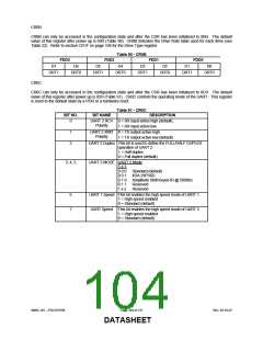
CR0B
CR0B can only be accessed in the configuration state and after the CSR has been initialized to 0BH. The default
value of this register after power up is 00H (Table 90). CR0B indicates the Drive Rate table used for each drive (see
Table 22). Refer to section CR1F on page 108 for the Drive Type register.
Table 90 - CR0B
FDD3
FDD2
FDD1
FDD0
D7
D6
D5
D4
D3
D2
D1
D0
DRT1
DRT0
DRT1
DRT0
DRT1
DRT0
DRT1
DRT0
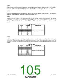
CR0C
CR0C can only be accessed in the configuration state and after the CSR has been initialized to 0CH. The default
value of this register after power up is 02H (Table 91). CR0C controls the operating mode of the UART. This register
is reset to the default state by a POR or a hardware reset.
Table 91 - CR0C
BIT NO.
BIT NAME
UART 2 RCV 0 = RX input active high (default).
Polarity
UART 2 XMIT 0 = TX output active high.
Polarity
DESCRIPTION
0
1 = RX input active low.
1
2
1 = TX output active low (default).
UART 2 Duplex This bit is used to define the FULL/HALF DUPLEX
operation of UART 2.
1 = Half duplex
0 = Full duplex (default)
3, 4, 5
UART 2 MODE UART 2 Mode
5 4 3
0 0 0 Standard (default)
0 0 1 IrDA (HPSIR)
0 1 0 Amplitude Shift Keyed IR @ 500Khz
0 1 1 Reserved
1 x x
Reserved
6
7
UART 1 Speed This bit enables the high speed mode of UART 1.
1 = High speed enabled
0 = Standard (default)
UART Speed This bit enables the high speed mode of UART 2.
1 = High speed enabled
0 = Standard (default)
SMSC DS – FDC37N769
Page 104 of 137
Rev. 02-16-07
DATASHEET

 SMSC [ SMSC CORPORATION ]