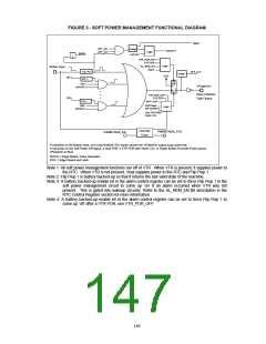
FIGURE 3 - SOFT POWER MANAGEMENT FUNCTIONAL DIAGRAM
nBINT
OFF_EN
OFF_DLY
Delay2
nSPOFF1
Logic
Button
nSPOFF
L
VTR_POR_EN
VTR POR
Logic
AL_REM_EN
Button Input
Alarm
ED; PG
OFF_DLY
Delay1
VTR
SP1
SPx
ED; L
EN1
Flip
Flop 1
D
nPowerOn
nSPOFF1
Q
CLR
Open Collector
Type Output
VTR_POR_OFF
VTR POR
VBAT POR
ED; L
ENx
nSPOFF1
Soft Power
Off nSPOFF1
Logic
VTR POR With
Vbat<1.2V
Override
Timer
PWRBTNOR_STS
PWRBTNOR_EN
nPowerOn output to go active low.
A transition on the Button input, or on any enabled SPx inputs causes the
A low pulse on the Soft Power Off signal, a Vbat POR, a VTR POR with Vbat<1.2V, or Power Button Override Event causes
nPowerOn to float.
ED;PG = Edge Detect, Pulse Generator
ED;L = Edge Detect and Latch
Note 1: All soft power management functions run off of VTR. When VTR is present, it supplies power to
the RTC. When VTR is not present, Vbat supplies power to the RTC and Flip Flop 1.
Note 2: Flip Flop 1 is battery backed-up so that it returns the last valid state of the machine.
Note 3: A battery backed-up enable bit in the alarm control register can be set to force Flip Flop 1 in the
soft power management circuit to come up ‘on’ if an alarm occurred when VTR was not
present. This is gated into wakeup circuitry. Refer to the AL_REM_EN Bit description in the
RTC Control Register section for more information.
Note 4: A battery backed-up enable bit in the alarm control register can be set to force Flip Flop 1 to
come up ‘off’ after a VTR POR, see VTR_POR_OFF.
149

 SMSC [ SMSC CORPORATION ]