Fan Control Device with High Frequency PWM Support and Hardware Monitoring Features
Datasheet
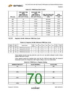
Table 8.31 PWM Ramp Rate Control
PWM RAMP TIME
PWM RAMP TIME
(SEC)
(SEC)
(TIME FROM 33%
DUTY CYCLE TO
100% DUTY CYCLE)
(TIME FROM 0%
DUTY CYCLE TO
100% DUTY CYCLE)
TIME PER PWM STEP
(PWM STEP SIZE =
1/255)
PWM
RAMP RATE
(HZ)
RRX-[2:0]
000
001
010
011
100
101
110
111
35
17.6
11.8
7.0
52.53
26.52
17.595
10.455
6.63
206 msec
104 msec
69 msec
41 msec
26 msec
18 msec
10 msec
5 msec
4.85
9.62
14.49
24.39
38.46
55.56
100
4.4
3.0
4.59
1.6
2.55
0.8
1.275
200
8.2.18
Registers 64-66h: Minimum PWM Duty Cycle
Table 8.32 Registers 64-66h: Minimum PWM Duty Cycle
Register
Address
Read/
Write
Bit 7
Bit 0
Default
Value
Register Name
Bit 6
Bit 5
Bit 4
Bit 3
Bit 2
Bit 1
(MSb)
(LSb)
64h
65h
66h
R/W
R/W
R/W
PWM1 Minimum Duty Cycle
PWM2 Minimum Duty Cycle
PWM3 Minimum Duty Cycle
7
7
7
6
6
6
5
5
5
4
4
4
3
3
3
2
2
2
1
1
1
0
0
0
80h
80h
80h
These registers become read only when the Lock bit is set. Any further attempts to write to these
registers shall have no effect.
These registers specify the minimum duty cycle that the PWM will output when the measured
temperature reaches the Temperature LIMIT register setting in Auto Fan Control Mode.
Table 8.33 PWM Duty vs. Register Setting
MINIMUM PWM DUTY
VALUE (DECIMAL)
VALUE (HEX)
0%
0
00h
.
.
.
.
.
.
.
.
.
25%
64
40h
.
.
.
.
.
.
.
.
.
50%
128
80h
.
.
.
.
.
.
.
.
.
100%
255
FFh
Revision 0.4 (04-04-05)
SMSC EMC6D103
DATA7S0HEET

 SMSC [ SMSC CORPORATION ]