Fan Control Device with High Frequency PWM Support and Hardware Monitoring Features
Datasheet
■
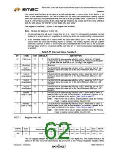
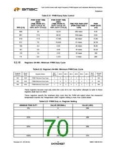
When in manual control mode, the PWMx Current Duty Cycle Registers (30h-32h) become
Read/Write. It is then possible to control the PWM outputs with software by writing to these
registers. See PWMx Current Duty Cycle Registers description.
■
■
When the fan is disabled (100) the corresponding PWM output is driven low (or high, if inverted).
When the fan is Full On (011) the corresponding PWM output is driven high (or low, if inverted).
Notes:
■
Zone 1 is controlled by Remote Diode 1 Temp Reading register
■
■
Zone 2 is controlled by Internal Temp Reading Register
Zone 3 is controlled by Remote Diode 2 Temp Reading register
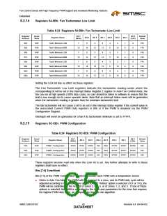
Table 8.25 Fan Zone Setting
ZON[7:5]
PWM CONFIGURATION
Fan on zone 1 auto
Fan on zone 2 auto
Fan on zone 3 auto
Fan always on full
000
001
010
011
100
101
110
111
Fan disabled
Fan controlled by hottest of zones 2,3
Fan controlled by hottest of zones 1,2,3
Fan manually controlled
Bit [4] PWM Invert
Bit [4] inverts the PWM output. If set to 1, 100% duty cycle will yield an output that is low for 255 clocks
and high for 1 clock. If set to 0, 100% duty cycle will yield an output that is high for 255 clocks and
low for 1 clock.
Bit [3] Reserved
Bits [2:0] Spin Up
Bits [2:0] specify the ‘spin up’ time for the fan. When a fan is being started from a stationary state, the
PWM output is held at 100% duty cycle for the time specified in Table 8.26, "Fan Spin-Up Register"
before scaling to a lower speed. Note: during spin-up, the PWM pin is forced high for the duration of
the spin-up time (i.e., 100% duty cycle = 256/256)
Note: To reduce the spin-up time, this device has implemented a feature referred to as Spin Up
Reduction. Spin Up Reduction uses feedback from the tachometers to determine when each
fan has started spinning properly. Spin up for a PWM will end when the tachometer reading
register is below the minimum limit, or the spin-up time expires, whichever comes first. All tachs
associated with a PWM must be below min. for spin-up to end prematurely. This feature can
be disabled by clearing bit 4 (SUREN) of the Configuration register (7Fh). If disabled, the all
fans go on full for the duration of their associated spin up time. Note that the Tachx minimum
registers must be programmed to a value less than FFFFh in order for the spin-up reduction
to work properly.
Revision 0.4 (04-04-05)
SMSC EMC6D103
DATA6S6HEET

 SMSC [ SMSC CORPORATION ]