Fan Control Device with High Frequency PWM Support and Hardware Monitoring Features
Datasheet
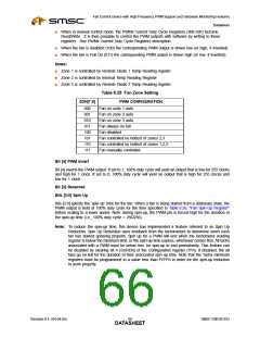
Table 8.26 Fan Spin-Up Register
SPIN[2:0]
SPIN UP TIME
000
001
010
011
100
101
110
111
0 sec
100ms
250ms (default)
400ms
700ms
1000ms
2000ms
4000ms
8.2.16
Registers 5F-61h: Zone Temperature Range, PWM Frequency
Table 8.27 Registers 5F-61h: Zone Temperature Range, PWM Frequency
Register
Address
Read/
Bit 7
Bit 0
Default
Value
Register Name
Bit 6
Bit 5
Bit 4
Bit 3
Bit 2
Bit 1
Write
(MSb)
(LSb)
5Fh
60h
61h
R/W
Zone 1 Range / Fan 1
Frequency
RAN3
RAN3
RAN3
RAN2
RAN1
RAN0
FRQ3
FRQ2
FRQ1
FRQ0
C3h
C3h
C3h
R/W
R/W
Zone 2 Range / Fan 2
Frequency
RAN2
RAN2
RAN1
RAN1
RAN0
RAN0
FRQ3
FRQ3
FRQ2
FRQ2
FRQ1
FRQ1
FRQ0
FRQ0
Zone 3 Range / Fan 3
Frequency
These registers become read only when the Lock bit is set. Any further attempts to write to these
registers shall have no effect.
In Auto Fan Mode, when the temperature for a zone is above the Low Temperature Limit (registers
67-69h) and below the Absolute Temperature Limit (registers 6A-6Ch) the speed of a fan assigned to
that zone is determined as follows by the auto fan control logic.
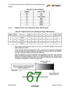
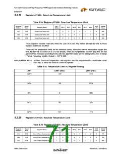
When the temperature reaches the temperature value programmed in the Zone x Low Temp Limit
register, the PWM output assigned to that zone is at PWMx Minimum Duty Cycle. Between Zone x
Low Temp Limit and (Zone x Low Temp Limit + Zone x Range), the PWM duty cycle increases linearly
according to the temperature as shown in the figure below.
PWM Duty is linear over
this range
Below Fan Temp Limit: Fan is off or at Fan PWM
Minimum depending on bit[7:5] of register 62h
and bit 2 of register 7Fh
Temperature
Temperature LIMIT: PWM
output at MIN FAN SPEED
LIMIT+ RANGE: PWM
Output at 100% Duty
Figure 8.1 Fan Activity Above Fan Temp Limit
SMSC EMC6D103
Revision 0.4 (04-04-05)
DATA6S7HEET

 SMSC [ SMSC CORPORATION ]