Fan Control Device with High Frequency PWM Support and Hardware Monitoring Features
Datasheet
Example for PWM1 assigned to Zone 1:
■
■
■
Zone 1 Low Temp Limit (Register 67h) is set to 50°C (32h).
Zone 1 Range (Register 5Fh) is set to 8°C (7h)
PWM1 Minimum Duty Cycle (Register 64h) is set to 50% (80h)
In this case, the PWM1 duty cycle will be 50% at 50°C.
Since (Zone 1 Low Temp Limit) + (Zone 1 Range) = 50°C + 8°C = 58°C, the fan controlled by PWM1
will run at 100% duty cycle when the temperature of the Zone 1 sensor is at 58°C.
Since the midpoint of the fan control range is 54°C, and the median duty cycle is 75% (Halfway
between the PWM Minimum and 100%), PWM1 duty cycle would be 75% at 54°C.
Above (Zone 1 Low Temp Limit) + (Zone 1 Range), the duty cycle must be 100%.
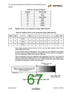
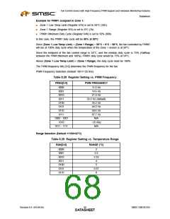
The PWM frequency bits [3:0] determine the PWM frequency for the fan.
PWM Frequency Selection (Default =0011=29.3Hz)
Table 8.28 Register Setting vs. PWM Frequency
FREQ[3:0]
PWM FREQUENCY
0000
0001
0010
0011
0100
0101
0110
0111
11.0 Hz
14.6 Hz
21.9 Hz
29.3 Hz (default)
35.2 Hz
44.0 Hz
58.6 Hz
87.7 Hz
N/A
1000 - 1001
1010
1011 - 1111
~25 Khz
N/A
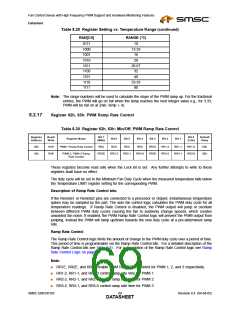
Range Selection (Default =1100=32°C)
Table 8.29 Register Setting vs. Temperature Range
RAN[3:0]
RANGE (°C)
0000
0001
0010
0011
0100
0101
0110
2
2.5
3.33
4
5
6.67
8
Revision 0.4 (04-04-05)
SMSC EMC6D103
DATA6S8HEET

 SMSC [ SMSC CORPORATION ]