Fan Control Device with High Frequency PWM Support and Hardware Monitoring Features
Datasheet
8.2.14
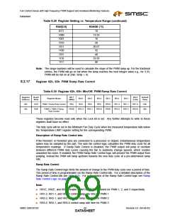
Registers 54-5Bh: Fan Tachometer Low Limit
Table 8.23 Registers 54-5Bh: Fan Tachometer Low Limit
Register
Address
Read/
Write
Bit 7
Bit 0
Default
Value
Register Name
Bit 6
Bit 5
Bit 4
Bit 3
Bit 2
Bit 1
(MSb)
(LSb)
54h
55h
56h
57h
58h
59h
5Ah
5Bh
R/W
R/W
R/W
R/W
R/W
R/W
R/W
R/W
Tach1 Minimum LSB
Tach1 Minimum MSB
Tach2 Minimum LSB
Tach2 Minimum MSB
Tach3 Minimum LSB
Tach3 Minimum MSB
Tach4 Minimum LSB
Tach4 Minimum MSB
7
15
7
6
14
6
5
13
5
4
12
4
3
11
3
2
10
2
1
9
1
9
1
9
1
9
0
8
0
8
0
8
0
8
FFh
FFh
FFh
FFh
FFh
FFh
FFh
FFh
15
7
14
6
13
5
12
4
11
3
10
2
15
7
14
6
13
5
12
4
11
3
10
2
15
14
13
12
11
10
Setting the Lock bit has no effect on these registers.
The Fan Tachometer Low Limit registers indicate the tachometer reading under which the
corresponding bit will be set in the Interrupt Status Register 2 register. In Auto Fan Control mode, the
fan can run at high speeds (100% duty cycle), so care should be taken in software to ensure that the
limit is low enough not to cause sporadic alerts. Note that an interrupt status event will be generated
when the tachometer reading is greater than the minimum tachometer limit.
The fan tachometer will not cause a bit to be set in the interrupt status register if the current value in
the associated Current PWM Duty registers is 00h or if the PWM is disabled via the PWM
Configuration Register.
Interrupts will never be generated for a fan if its tachometer minimum is set to FFFFh.
8.2.15
Registers 5C-5Eh: PWM Configuration
Table 8.24 Registers 5C-5Eh: PWM Configuration
Register
Address
Read/
Write
Bit 7
Bit 0
Default
Value
Register Name
Bit 6
Bit 5
Bit 4
Bit 3
Bit 2
Bit 1
(MSb)
(LSb)
5Ch
5Dh
5Eh
R/W
R/W
R/W
PWM 1 Configuration
PWM 2 Configuration
PWM 3 Configuration
ZON2
ZON2
ZON2
ZON1
ZON1
ZON1
ZON0
ZON0
ZON0
INV
INV
INV
RES
RES
RES
SPIN2
SPIN2
SPIN2
SPIN1
SPIN1
SPIN1
SPIN0
SPIN0
SPIN0
62h
62h
62h
These registers become read only when the Lock bit is set. Any further attempts to write to these
registers shall have no effect.
Bits [7:5] Zone/Mode
Bits [7:5] of the PWM Configuration registers associate each PWM with a temperature sensor.
■
When in Auto Fan Mode, the PWM will be assigned to a zone, and its PWM duty cycle will be
adjusted according to the temperature of that zone. If ‘Hottest’ option is selected (101 or 110), the
PWM will be controlled by the hottest of zones 2 and 3, or of zones 1, 2, and 3. If one of these
options is selected, the PWM is controlled by the limits and parameters for the zone that requires
the highest PWM duty cycle, as computed by the auto fan algorithm.
SMSC EMC6D103
Revision 0.4 (04-04-05)
DATA6S5HEET

 SMSC [ SMSC CORPORATION ]