Fan Control Device with High Frequency PWM Support and Hardware Monitoring Features
Datasheet
Note 7.1 This max value will be FFFFh if the programmed number of edges is detected when the
count reaches FFFFh or if no edges are detected. If the count reaches FFFFh in Mode 1
and some edges were detected, but less than the programmed number of edges, the
maximum tach count value is determined by the Slow Interrupt Enable bit located in the
TACHx Options registers at offsets 90h to 93h. If slow interrupt detection is set to 0, the
count will be forced to FFFEh, else the count will be forced to FFFFh.
7.1.4.8
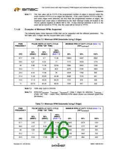
Examples of Minimum RPMs Supported
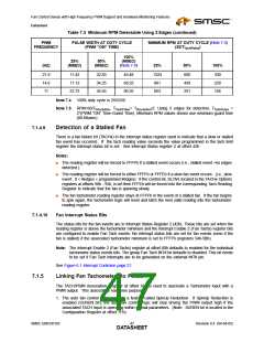
The following tables show minimum RPMs that can be supported with the different parameters. The
first table uses 3 edges and the second table uses 2 edges.
Table 7.2 Minimum RPM Detectable Using 3 Edges
PWM
PULSE WIDTH AT DUTY CYCLE
(PWM ”ON” TIME)
MINIMUM RPM AT DUTY CYCLE (Note 7.3)
(30/TTachPulse
FREQUENCY
)
100%
25%
50%
(MSEC)
(HZ)
(MSEC)
(MSEC)
(Note 7.2)
25%
50%
100%
87.7
58.6
44
2.85
4.27
5.68
7.1
5.7
11.36
17
10865
7175
5366
4279
3554
2648
1761
1325
5347
3554
2662
2126
1768
1319
878
2662
1774
1330
1063
885
8.53
11.36
14.2
22.64
28.3
34
35.2
29.3
21.9
14.6
11
8.53
11.42
17.12
22.73
17.06
22.83
34.25
45.45
45.48
68.23
90.55
661
440
661
332
Note 7.2 100% duty cycle is 255/256.
Note 7.3 RPM=60/TRevolution, TTachPulse= TRevolution/2. Using 3 edges for detection, TTachPulse
=
(PWM ”ON” Time – Guard Time). Minimum RPM values shown use minimum guard time
(88.88usec).
Table 7.3 Minimum RPM Detectable Using 2 Edges
PWM
PULSE WIDTH AT DUTY CYCLE
(PWM ”ON” TIME)
MINIMUM RPM AT DUTY CYCLE (Note 7.5)
(30/TTachPulse
FREQUENCY
)
100%
25%
50%
(MSEC)
(HZ)
(MSEC)
(MSEC)
(Note 7.4)
25%
50%
100%
87.7
58.6
44
2.85
4.27
5.68
7.1
5.7
11.36
17
5433
3588
2683
2139
1777
2673
1777
1331
1063
884
1331
887
665
532
442
8.53
11.36
14.2
22.64
28.3
34
35.2
29.3
8.53
17.06
Revision 0.4 (04-04-05)
SMSC EMC6D103
DATA4S6HEET

 SMSC [ SMSC CORPORATION ]