Fan Control Device with Hardware Monitoring and Acoustic Noise Reduction Features
Datasheet
which is used to enable thermal events to force the interrupt pin (INT#) low if interrupts are enabled
(see Bit[2] INTEN of the Special Function register at offset 7Ch).
This register contains the following bits:
Bit[0] TEMP. Group temperature enable bit.
0=Out-of-limit temperature readings do not affect the state of the INT# pin (default)
1=Enable out-of-limit temperature readings to make the INT# pin active low
Bit[1] Ambient Temperature Status Enable bit.
Bit[2] Remote Diode 1 Temperature Status Enable bit.
Bit[3] Remote Diode 2 Temperature Status Enable bit
Bit[4] Reserved
Bit[5] Reserved
Bit[6] Reserved
Bit[7] Reserved
The individual thermal error event bits are defined as follows:
0=disable
1=enable.
See Figure 5.1 Interrupt Control on page 22.
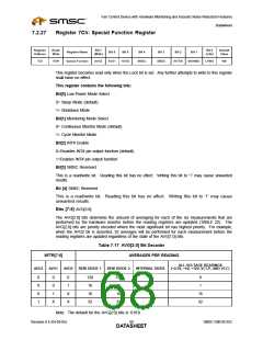
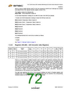
7.2.33
Registers 85h-88h: A/D Converter LSbs Registers
Register
Address
Read/
Write
Register
Name
Bit 7
Bit 0
Default
Value
Bit 6
Bit 5
Bit 4
Bit 3
Bit 2
Bit 1
(MSb)
(LSb)
85h
86h
87h
88h
R
R
R
R
A/D Converter LSbs Reg 1
A/D Converter LSbs Reg 2
A/D Converter LSbs Reg 3
A/D Converter LSbs Reg 4
RD2.3
V12.3
V50.3
VCC.3
RD2.2
V12.2
V50.2
VCC.2
RD2.1
V12.1
V50.1
VCC.1
RD2.0
V12.0
V50.0
VCC.0
RD1.3
AM.3
RD1.2
AM.2
RD1.1
AM.1
RD1.0
AM.0
N/A
N/A
N/A
N/A
V25.3
VCP.3
V25.2
VCP.2
V25.1
VCP.1
V25.0
VCP.0
There is a 10-bit Analog to Digital Converter (ADC) located in the hardware monitoring block that
converts the measured voltages into 10-bit reading values. Depending on the averaging scheme
enabled, the hardware monitor may take multiple readings and average them to create the values
stored in the reading registers (i.e., 16x averaging, 32x averaging, etc.) The 8 MSb’s of the reading
values are placed in the Reading Registers. When the upper 8-bits located in the reading registers
are read the 4 LSb’s are latched into their respective bits in the A/D Converter LSbs Register. This
give 12-bits of resolution with a minimum value of 1/16th per unit measured. (i.e., Temperature Range:
-127.9375 ºC < Temp < 127.9375 ºC and Voltage Range: 0 < Voltage < 256.9375) . See the DC
Characteristics for the accuracy of the reading values.
The eight most significant bits of the 12-bit averaged readings are stored in Reading registers and
compared with Limit registers. The Interrupt Status Register bits are asserted if the corresponding
measured value(s) on the inputs violate their programmed limits.
Revision 0.4 (04-05-05)
SMSC EMC6D102
DATA7S2HEET

 SMSC [ SMSC CORPORATION ]