Fan Control Device with Hardware Monitoring and Acoustic Noise Reduction Features
Datasheet
Note: PWM Max stretch time determines the maximum time for monitoring the tach input. If
stretching is disabled, the tach will only be monitored when the PWM duty cycle is ‘ON’. For
a complete definition of stretching see section PWM Stretching on page 38.
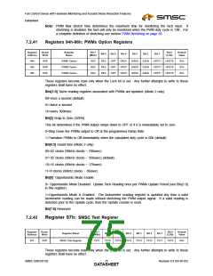
7.2.41
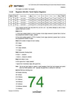
Registers 94h-96h: PWMx Option Registers
Register
Address
Read/
Write
Register
Name
Bit 7
Bit 0
Default
Value
Bit 6
Bit 5
Bit 4
Bit 3
Bit 2
Bit 1
(MSb)
(LSb)
94h
95h
96h
R/W
R/W
R/W
PWM1 Option
PWM2 Option
PWM3 Option
RES
RES
RES
RES
RES
RES
OPP
OPP
OPP
GRD1
GRD1
GRD1
GRD0
GRD0
GRD0
SZEN
SZEN
SZEN
UPDT1
UPDT1
UPDT1
UPDT0
UPDT0
UPDT0
0Ch
0Ch
0Ch
These registers become read only when the Lock bit is set. Any further attempts to write to these
registers shall have no effect.
Bits[1:0] Tachs reading registers associated with PWMx are updated: (Mode 2 only)
00=once a second (default)
01=twice a second
1x=every 300msec
Bit[2] Snap to Zero (SZEN)
This bit determines if the PWM output ramps down to OFF or if it is immediately set to zero.
0=Step Down the PWMx output to Off at the programmed Ramp Rate
1=Transition PWMx to Off immediately when the calculated duty cycle is 00h (default)
Bit[4:3] Guard time (Mode 2 only)
00=63 clocks (90kHz clocks ~ 700usec)
01=32 clocks (90kHz clocks ~ 356usec) (default)
10=16 clocks (90kHz clocks ~ 178usec)
11=8 clocks (90kHz clocks ~ 89usec)
Bit[5] Opportunistic Mode Enable
0= Opportunistic Mode Disabled. Update Tach Reading once per PWMx Update Period (see Bits[1:0]
in this register)
1=Opportunistic Mode is Enabled. The tachometer reading register is updated any time a valid
tachometer reading can be made without stretching the PWM output signal. If a valid reading is
detected prior to the Update cycle, then the Update counter is reset.
Bit[7:6] Reserved
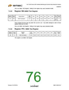
7.2.42
Register 97h: SMSC Test Register
Register
Address
Read/
Write
Bit 7
Bit 0
Default
Value
Register Name
Bit 6
Bit 5
Bit 4
Bit 3
Bit 2
Bit 1
(MSb)
(LSb)
97h
R/W
SMSC Test Register
TST7
TST6
TST5
TST4
TST3
TST2
TST1
TST0
5Ah
These registers become read only when the Lock bit is set. Any further attempts to write to these
registers shall have no effect.
SMSC EMC6D102
Revision 0.4 (04-05-05)
DATA7S5HEET

 SMSC [ SMSC CORPORATION ]