Fan Control Device with Hardware Monitoring and Acoustic Noise Reduction Features
Datasheet
This register is an SMSC Test register.
7.2.40
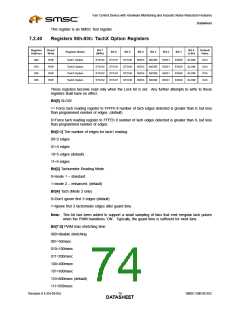
Registers 90h-93h: TachX Option Registers
Register
Address
Read/
Bit 7
Bit 0
Default
Value
Register Name
Bit 6
Bit 5
Bit 4
Bit 3
Bit 2
Bit 1
Write
R/W
R/W
R/W
R/W
(MSb)
(LSb)
90h
91h
92h
93h
Tach1 Option
Tach2 Option
Tach3 Option
Tach4 Option
STCH2
STCH2
STCH2
STCH2
STCH1
STCH1
STCH1
STCH1
STCH0
STCH0
STCH0
STCH0
3EDG
3EDG
3EDG
3EDG
MODE
MODE
MODE
MODE
EDG1
EDG1
EDG1
EDG1
EDG0
EDG0
EDG0
EDG0
SLOW
SLOW
SLOW
SLOW
CCh
CCh
CCh
CCh
These registers become read only when the Lock bit is set. Any further attempts to write to these
registers shall have no effect.
Bit[0] SLOW
1= Force tach reading register to FFFFh if number of tach edges detected is greater than 0, but less
than programmed number of edges. (default)
0=Force tach reading register to FFFEh if number of tach edges detected is greater than 0, but less
than programmed number of edges.
Bit[2:1] The number of edges for tach1 reading:
00=2 edges
01=3 edges
10=5 edges (default)
11=9 edges
Bit[3] Tachometer Reading Mode
0=mode 1 – standard
1=mode 2 – enhanced. (default)
Bit[4] Tach (Mode 2 only)
0=Don’t ignore first 3 edges (default)
1=Ignore first 3 tachometer edges after guard time
Note: This bit has been added to support a small sampling of fans that emit irregular tach pulses
when the PWM transitions ‘ON’. Typically, the guard time is sufficient for most fans.
Bit[7:5] PWM max stretching time
000=disable stretching
001=50msec
010=100msec
011=200msec
100=400msec
101=600msec
110=800msec (default)
111=950msec
Revision 0.4 (04-05-05)
SMSC EMC6D102
DATA7S4HEET

 SMSC [ SMSC CORPORATION ]