Fan Control Device with Hardware Monitoring and Acoustic Noise Reduction Features
Datasheet
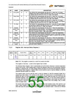
Diode 2 Limit Error) in addition to the diode fault bit. Disabling the enable bit for the diode will clear
both the fault bit and the error bit for that diode (see Note below).
This register is read only – a write to this register has no effect.
Note:
Clearing the individual enable bits:
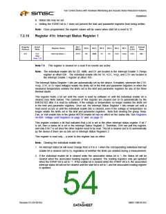
1. An interrupt status bit will never change from a 0 to a 1 when the corresponding individual interrupt
enable bit is cleared (set to 0), regardless of whether the limits are violated during a measurement.
2. If the individual enable bit is cleared while the associated status bit is 1, the status bit will be
cleared when the associated reading register is updated. The reading registers only get updated
when the START bit is set to ‘1’. If the enable bit is cleared when the START bit is 0, the associated
interrupt status bit will not be cleared until the start bit is set to 1 and the associated reading register
is updated.
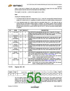
BIT
NAME
R/W DEFAULT
DESCRIPTION
0
+12v_Error
R
0
The EMC6D102 automatically sets this bit to 1 when the 12V input
voltage is less than or equal to the limit set in the 12V Low Limit register
or greater than the limit set in the 12V High Limit register.
1
2
Reserved
R
R
0
0
Reserved
TACH1
The EMC6D102 automatically sets this bit to 1 when the TACH1 input
reading is above the value set in the Tach1 Minimum MSB and LSB
registers.
Slow/Stalled
3
4
5
6
TACH2
R
R
R
R
0
0
0
0
The EMC6D102 automatically sets this bit to 1 when the TACH2 input
reading is above the value set in the Tach2 Minimum MSB and LSB
registers.
The EMC6D102 automatically sets this bit to 1 when the TACH3 input
reading is above the value set in the Tach3 Minimum MSB and LSB
registers.
The EMC6D102 automatically sets this bit to 1 when the TACH4 input
reading is above the value set in the Tach4 Minimum MSB and LSB
registers.
The EMC6D102 automatically sets this bit to 1 when there is either a
short or open circuit fault on the Remote1+ or Remote1- thermal diode
input pins as defined in the section Diode Fault on page 22.
Slow/Stalled
TACH3
Slow/Stalled
TACH4
Slow/Stalled
Remote
Diode 1 Fault
Note:
If the START bit is set and a fault condition exists, the Remote
Diode 1 reading register will be forced to 80h.
7
Remote
R
0
The EMC6D102 automatically sets this bit to 1 when there is either a
short or open circuit fault on the Remote2+ or Remote2- thermal diode
input pins as defined in the section Diode Fault on page 22.
Diode 2 Fault
Note:
If the START bit is set and a fault condition exists, the Remote
Diode 2 reading register will be forced to 80h.
7.2.12
Register 43h: VID
Register
Address
Read/
Bit 7
Bit 0
Default
Value
Register Name
Bit 6
Bit 5
Bit 4
Bit 3
Bit 2
Bit 1
Write
(MSb)
(LSb)
43h
R
VID0-4
RES
RES
RES
VID4
VID3
VID2
VID1
VID0
N/A
The VID register contains the values of EMC6D102 VID0-VID4 input pins. This register indicates the
status of the VID lines that interconnect the processor to the Voltage Regulator Module (VRM).
Software uses the information in this register to determine the voltage that the processor is designed
to operate at. With this information, software can then dynamically determine the correct values to
place in the Vccp Low Limit and Vccp High Limit registers.
Revision 0.4 (04-05-05)
SMSC EMC6D102
DATA5S6HEET

 SMSC [ SMSC CORPORATION ]