Legacy-Free Keyboard/Embedded Controller with SPI and LPC Docking Interface
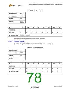
7.8.3.4
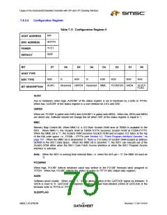
Configuration Register
Table 7.11 Configuration Register 0
N/A
HOST ADDRESS
8051 ADDRESS
POWER
0x7FF4
VCC1
0x00
DEFAULT
BIT
D7
D6
D5
D4
D3
D2
D1
D0
-
-
-
-
-
-
-
-
HOST TYPE
8051 TYPE
R/W
R
R/W
R
R/W
R/W
R/W
R/W
AUXH
Reserved OBFEN Reserved MMC
PCOBFEN SAEN
SLEEP
FLAG
BIT DESCRIPTION
AUXH
Aux in Hardware; when high, AUXOBF of the status register is set in hardware by a write to 7FFAh.
When low, AUXOBF of the status register is a user defined bit (UD) and R/W.
OBFEN
When set, PCOBF is gated onto KIRQ and AUXOBF1 is gated onto MIRQ. When low, KIRQ and MIRQ
are driven low. Software should not change this bit when OBF of the status register is equal to 1.
MMC
Memory Map Control Bit: When MMC=0, a 512 Byte Scratch RAM area at 7B00h is available to the
8051. When MMC=1, the Scratch RAM at 7B00h-7CFFh becomes Scratch ROM at FE00h-FFFFh.
When the MMC bit is ‘1’, the Scratch RAM becomes Scratch ROM and occupies 512 bytes at the top
of the 64k code space; i.e., FE00h – FFFFh (see Section 9.2, "Flash Program Interface Decoder," on
page 107. When the MMC bit is deasserted ‘0’, there is 512 bytes of Scratch RAM located at address
0x7B00 in the 8051 Data Space. When the MMC bit is asserted ‘1’, the 8051 can execute out of the
Scratch ROM either when the 8051 Code Fetch Access interface or when the 8051 Program Access
interface is selected.
Note: When the 8051 is running from external flash, i.e. when the nEA pin = ‘0’, the MMC bit must be
‘0’.
PCOBFEN
When high, PCOBF reflects whatever value was written to the PCOBF firmware latch assigned to
7FFDH. When low, PCOBF reflects the status of writes to 7FF1H (the output data register).
SAEN
Software-assist enable. When set to “1,” SAEN allows control of the GATEA20 signal via firmware. If
SAEN is reset to ‘0’, GATEA20 corresponds to either the last host-initiated control of GATEA20 or the
firmware write to 7FFEh or 7FFFh.
SLEEPFLAG
SMSC LPC47N350
Revision 1.1 (01-14-03)
DATA6S1HEET

 SMSC [ SMSC CORPORATION ]