Legacy-Free Keyboard/Embedded Controller with SPI and LPC Docking Interface
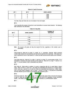
Table 5.4 Serial Character
BIT 1
BIT 0
WORD LENGTH
0
0
1
1
0
1
0
1
5 Bits
6 Bits
7 Bits
8 Bits
The Start, Stop and Parity bits are not included in the word length.
BIT 2
This bit specifies the number of stop bits in each transmitted or received serial character. The following
table summarizes the information.
Table 5.5 Stop Bits
NUMBER OF
BIT 2
WORD LENGTH
STOP BITS
0
1
--
1
1.5
2
5 bits
6 bits
7 bits
8 bits
Note: The receiver will ignore all stop bits beyond the first, regardless of the number used in
transmitting.
BIT 3
Parity Enable bit. When bit 3 is a logic "1", a parity bit is generated (transmit data) or checked
(receive data) between the last data word bit and the first stop bit of the serial data. (The parity bit is
used to generate an even or odd number of 1s when the data word bits and the parity bit are summed).
BIT 4
Even Parity Select bit. When bit 3 is a logic "1" and bit 4 is a logic "0", an odd number of logic "1"'s is
transmitted or checked in the data word bits and the parity bit. When bit 3 is a logic "1" and bit 4 is a
logic "1", an even number of bits is transmitted and checked.
BIT 5
Stick Parity bit. When parity is enabled, it is used in conjunction with bit 4 to select Mark or Space
Parity. When LCR bits 3, 4 and 5 are 1, the Parity bit is transmitted and checked as a 0 (Space Parity).
If bits 3 and 5 are 1 and bit 4 is a 0, then the Parity bit is transmitted and checked as 1 (Mark Parity).
If bit 5 is 0 Stick Parity is disabled. Bit 3 is a logic "1" and bit 5 is a logic "1", the parity bit is transmitted
and then detected by the receiver in the opposite state indicated by bit 4.
BIT 6
Set Break Control bit. When bit 6 is a logic "1", the transmit data output (TXD) is forced to the Spacing
or logic "0" state and remains there (until reset by a low level bit 6) regardless of other transmitter
activity. This feature enables the Serial Port to alert a terminal in a communications system.
BIT 7
SMSC LPC47N350
Revision 1.1 (01-14-03)
DATA2S9HEET

 SMSC [ SMSC CORPORATION ]