Legacy-Free Keyboard/Embedded Controller with SPI and LPC Docking Interface
3.1.7
3.1.8
I/O Start Fields
I/O cycles use a START field of 0000.
Reset Policy
The following rules govern the reset policy:
1. When LRESET# goes inactive (high), the clock is assumed to have been running for 100usec prior
to the removal of the reset signal, so that everything is stable. This is the same reset active time
after clock is stable that is used for the PCI bus.
2. When LRESET# goes active (low):
a. the host drives the LFRAME# signal high and tristates the LAD[3:0] signals.
b. LPC47N350 ignores LFRAME# and tristates the LAD[3:0] pins.
3.1.9
Electrical Specifications
The LPC interface uses 3.3V signaling. No output from the peripheral may drive higher than 3.3V
nominal. See the Intel Low Pin Count Specification.
3.1.10 Wait State Requirements
3.1.10.1 I/O Transfers
Wait states are required for all I/O transfers. Three wait states are required for an I/O read and two wait
states are required for an I/O write. A SYNC of 0110 is used for all I/O transfers.
3.1.11 LPC Transfer I/O Sequence Examples
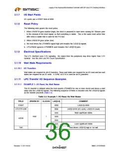
3.1.11.1 EXAMPLE 1: I/O Read, No Wait States
The I/O transfer is initiated when the host asserts LFRAME# for one or more clocks and drives a start
value onto the LAD[3:0] signals. The following sequence of fields is encoded onto the LAD[3:0] signals
as the transfer proceeds (Table 3.4):
Table 3.4 Example 1: I/O Read, No Wait States
FIELD
DRIVEN BY
CLOCKS
LAD[3:0]
COMMENT
START
0000
000x
xxxx
xxxx
xxxx
xxxx
1111
LAD[3:0]=0000
LAD[3:2]=00 (I/O cycle), LAD[1]=0 (read)
Most significant nibble
CYCTYP+DIR
Host
1
ADDR
TAR
Least significant nibble
Host drives LAD[3:0] high in 1st half
Revision 1.1 (01-14-03)
SMSC LPC47N350
DATA1S8HEET

 SMSC [ SMSC CORPORATION ]