Legacy-Free Keyboard/Embedded Controller with SPI and LPC Docking Interface
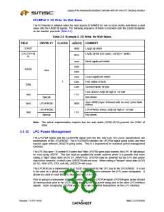
terminated. No data is to be transferred to the host on I/O reads, and the data written to the
LPC47N350 on I/O writes and DMA reads is to be ignored. Note that once the LPC47N350
asserts the ready SYNC, the host will not abort.
3.1.5
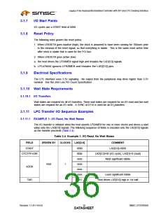
I/O Read and Write Cycles
I/O cycles are initiated by the host for register or FIFO accesses and will generally have minimal Sync
times. The minimum number of wait-states between bytes is 1. EPP cycles will depend on the speed
of the external device, and may have much longer Sync times.
Data transfers are assumed to be exactly 1-byte. If the CPU requested a 16 or 32-bit transfer, the host
will break it up into 8-bit transfers.
3.1.6
SYNC Protocol
See the Intel Low Pin Count Specification for a table of valid SYNC values.
3.1.6.1
Typical SYNC Usage
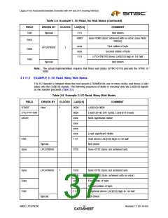
The SYNC pattern is used to add wait states. For read cycles, the LPC47N350 immediately drives the
SYNC pattern upon recognizing the cycle. The host immediately drives the sync pattern for write cycles.
If the LPC47N350 needs to assert wait states, it does so by driving 0101 or 0110 on LAD[3:0] until it is
ready, at which point it will drive 0000 or 1001. On any particular access, the LPC47N350 chooses to
assert 0101 or 0110, but not switch between the two patterns.
The data will immediately follow the 0000 or 1001 value. If no wait states are needed, the LPC47N350
just drives 0000 or 1001 followed by the data. Because the SYNC pattern of 0000 or 1001 is always
required, there is effectively a minimum of 1 wait state for accesses.
The SYNC value of 0101 is used for normal wait states, wherein the cycle will complete within a few
clocks.
The SYNC value of 0110 is used where the number of wait states is large.
The SYNC value must be driven within 3 clocks.
3.1.6.2
SYNC Timeout
The SYNC value is driven within 3 clocks. If the host observes 3 consecutive clocks without a valid
SYNC pattern, it will abort the cycle. The LPC47N350 does not assume any particular timeout. When
the host is driving SYNC, it may have to insert a very large number of wait states, depending on PCI
latencies and retries.
3.1.6.3
3.1.6.4
Sync Patterns and Maximum Number of Syncs
If the SYNC pattern is 0101, then the host assumes that the maximum number of SYNCs is 8.
If the SYNC pattern is 0110, then no maximum number of SYNCs is assumed. The LPC47N350 must
have protection mechanisms to complete the cycle.
Sync Error Indication
The peripheral reports errors via the LAD[3:0] = 1010 SYNC encoding.
If the host was reading data from the peripheral, data will still be transferred in the next two nibbles.
This data may be invalid, but it is transferred by the LPC47N350. If the host was writing data to the
LPC47N350, the data had already been transferred.
In the case of multiple byte cycles, such as memory cycles, an error SYNC terminates the cycle.
Therefore, if the host is transferring 4 bytes from a device or if the device returns the error SYNC in the
first byte, the other three bytes will not be transferred.
SMSC LPC47N350
Revision 1.1 (01-14-03)
DATA1S7HEET

 SMSC [ SMSC CORPORATION ]