Legacy-Free Keyboard/Embedded Controller with SPI and LPC Docking Interface
B.3.3
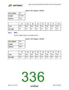
DPS
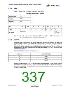
The DPS register (Table B.4) is used to select the active DPTR
Table B.4 DPS Register - SFR 86h
86h
SFR ADDRESS
POWER
VCC1
0x00
DEFAULT
BIT
D7
D6
D5
D4
D3
D2
D1
D0
R
R
R
R
R
R
R
TYPE
RESERVED
SEL
BIT NAME
(Note B.1
Note B.1 When SEL = ‘0’, instructions that use the DPTR will use DPL0 and DPH0. When SEL = ‘1’,
instructions that use the DPTR will use DPL1 and DPH1.
B.3.4
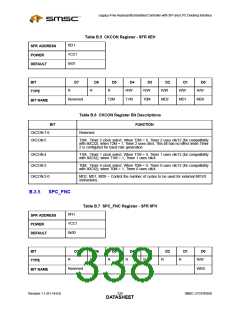
CKCON
The default timer clock scheme for the DW8051 timers is 12 clk cycles per increment, the same as in
the standard 8051. However, in the DW8051, the instruction cycle is 4 clk cycles. Using the default rate
(12 clocks per timer increment) allows existing application code with real-time dependencies, such as
baud rate, to operate properly. However, applications that require fast timing can set the timers to
increment every 4 clk cycles by setting bits in the Clock Control register (CKCON) at SFR location 8Eh
(Table B.5 and Table B.6)
The CKCON bits that control the timer clock rates are:
CKCON BIT
COUNTER/TIMER
5
4
3
Timer 2
Timer 1
Timer 0
When a CKCON register bit is set to 1, the associated counter increments at 4-clk intervals. When a
CKCON bit is cleared, the associated counter increments at 12-clk intervals. The timer controls are
independent of each other. The default setting for all three timers is 0 (12-clk intervals). These bits have
no effect in counter mode.
SMSC LPC47N350
319
Revision 1.1 (01-14-03)
DATASHEET

 SMSC [ SMSC CORPORATION ]