Legacy-Free Keyboard/Embedded Controller with SPI and LPC Docking Interface
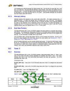
Table B.1 Timer 2 Mode Control Summary (continued)
RCLK
TCLK
TR2
MODE
X
1
1
0
Baud Rate Generator
Off
X
B.2.2
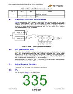
16-Bit Timer/Counter Mode with Auto-Reload
Figure B.1 illustrates how Timer 2 operates in timer/counter mode with auto-reload. The 16-bit timer
counts CLK cycles (divided by 4 or 12). The TR2 bit enables the counter. When the count increments
from FFFFh, the overflow occurs. The overflow causes the TF2 flag is set, and t2_out goes high for one
CLK cycle. The overflow also causes the preloaded start value in the RCAP2L and RCAP2H registers
to be reloaded into the TL2 and TH2 registers.
T2M
DIVIDE BY 12
0
CLK
clk
TL2
TH2
1
TF2
INT
TR2
DIVIDE BY 4
RCAP2L
RCAP2H
Figure B.1 Timer 2 Timer/Counter with Auto-Reload
B.2.3
Baud Rate Generator Mode
Setting either RCLK or TCLK to 1 configures Timer 2 to generate baud rates for Serial Port 0 in serial
mode 1 or 3. In baud rate generator mode, Timer 2 functions in auto-reload mode. However, instead
of setting the TF2 flag, the counter overflow is used to generate a shift clock for the serial port function.
As in normal auto-reload mode, the overflow also causes the preloaded start value in the RCAP2L and
RCAP2H registers to be reloaded into the TL2 and TH2 registers.
When either TCLK = 1 or RCLK = 1, Timer 2 is forced into auto-reload operation. The counter time
base in baud rate generator mode is clk/2.
B.3
Special Function Registers
The following SFRs are not part of the standard 8051 architecture.
B.3.1
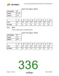
DPL1
The DPL1 register (Table B.2) is the LSB of DPTR1.
SMSC LPC47N350
317
Revision 1.1 (01-14-03)
DATASHEET

 SMSC [ SMSC CORPORATION ]