Legacy-Free Keyboard/Embedded Controller with SPI and LPC Docking Interface
The remaining four external interrupts are edge-sensitive only. int2 and int4 are active high, int3_n and
int5_n are active low. The power-fail (pfi) interrupt is edge-sensitive, active high, and sampled once per
instruction cycle. To ensure that edge-sensitive interrupts are detected, the corresponding ports should
be held high for 4 clk cycles and then low for 4 clk cycles. Level-sensitive interrupts are not latched
and must remain active until serviced.
B.1.5
B.1.6
Interrupt Latency
Interrupt response time depends on the current state of the 8051. The fastest response time is 5
instruction cycles: 1 to detect the interrupt, and 4 to perform the LCALL to the ISR. The maximum
latency (13 instruction cycles) occurs when the 8051 is currently executing a RETI instruction followed
by a MUL or DIV instruction. The 13 instruction cycles in this case are: 1 to detect the interrupt, 3 to
complete the RETI, 5 to execute the DIV or MUL, and 4 to execute the LCALL to the ISR. For the
maximum latency case, the response time is 13 x 4 = 52 clk cycles.
Dual Data Pointers
The high-performance 8051 in the LPC47N350 employs dual data pointers to accelerate data memory
block moves. The standard 8051 data pointer (DPTR) is a 16-bit value used to address external RAM
or peripherals. The LPC47N350 maintains the standard data pointer as DPTR0 at SFR locations 82h
and 83h. It is not necessary to modify code to use DPTR0.
The LPC47N350 adds a second data pointer (DPTR1) at SFR locations 84h and 85h. The SEL bit in
the DPTR Select Register, DPS (SFR 86h), selects the active pointer (see Section B.3.1, "DPL1",
Section B.3.2, "DPH1" and Section B.3.3, "DPS").
All DPTR-related instructions use the currently selected data pointer. To switch the active pointer, toggle
the SEL bit. The fastest way to do so is to use the increment instruction (INC DPS). This requires only
one instruction to switch from a source address to a destination address, saving application code from
having to save source and destination addresses when doing a block move.
B.2
Timer 2
B.2.1
Overview
The high-performance 8051 in the LPC47N350 includes a third timer/counter (Timer 2). Timer 2 runs
only in 16-bit mode and offers several capabilities not available with Timers 0 and 1. The modes
available with Timer 2 are 16-bit auto-reload timer/counter and baud rate generator. The SFRs
associated with Timer 2 are:
T2CON (SFR C8h)
RCAP2L (SFR CAh) – Used as the 16-bit LSB reload value when Timer 2 is configured for auto-reload
mode.
RCAP2H (SFR CBh) – Used as the 16-bit MSB reload value when Timer 2 is configured for auto-reload
mode.
TL2 (SFR CCh) – Lower 8 bits Table 332-bit count.
TH2 (SFR CDh) – Upper 8 bits of 16-bit count.
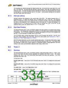
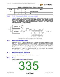
Table B.1 summarizes how the T2CON SFR bits (Table B.11) determine the Timer 2 operating mode.
Table B.1 Timer 2 Mode Control Summary
RCLK
TCLK
TR2
MODE
0
1
0
1
16-bit Timer/Counter w/Auto-reload
Baud Rate Generator
X
Revision 1.1 (01-14-03)
316
SMSC LPC47N350
DATASHEET

 SMSC [ SMSC CORPORATION ]