Legacy-Free Keyboard/Embedded Controller with SPI and LPC Docking Interface
29.5
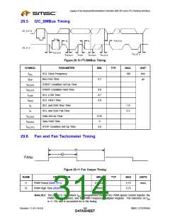
I2C_SMBus Timing
AB_D ATA
tLOW
tBUF
tH D;STA
tR
tF
AB_C LK
tH D;STA
tSU;STO
tH D;DAT
tH IG H
tSU;DAT
tSU;STA
2
Figure 29.10 I C/SMBus Timing
SYMBOL
fSCL
tBUF
PARAMETER
MIN.
TYP.
MAX.
UNIT
SCL Clock Frequency
Bus Free Time
100
kHz
µs
4.7
tSU;STA
tHD;STA
tLOW
START Condition Set-Up Time
START Condition Hold Time
SCL LOW Time
4.0
4.7
4.0
tHIGH
tR
SCL HIGH Time
SCL and SDA Rise Time
SCL and SDA Fall Time
Data Set-Up Time
1.0
0.3
tF
tSU;DAT
tHD;DAT
tSU;STO
0.25
0
Data Hold Time
STOP Condition Set-Up Time
4.0
29.6
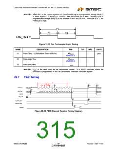
Fan and Fan Tachometer Timing
t1
t2
FANx
Figure 29.11 Fan Output Timing
NAME
DESCRIPTION
MIN
TYP
MAX
UNITS
t1
t2
PWM Period (Note 29.2)
0.0254
5.75
5.75
msec
PWM High Time (Note 29.3)
0.00039
Note 29.2 The period is 1/fout,where fout is programmed through the PWM Speed Control register, the
PWM Control registers, and the PWM Frequency Multiplier Register. The tolerance on fout
is +/- 5% and is accounted for in the timing.
Revision 1.1 (01-14-03)
296
SMSC LPC47N350
DATASHEET

 SMSC [ SMSC CORPORATION ]