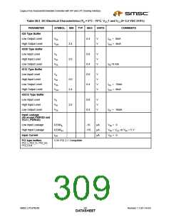
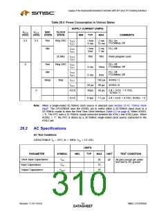
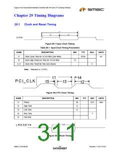
Legacy-Free Keyboard/Embedded Controller with SPI and LPC Docking Interface
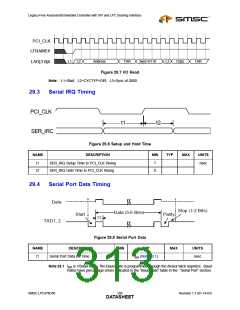
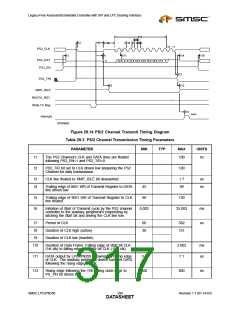
PCI_CLK
LFRAME#
L1 L2
Address
TAR
Sync=0110
L3
Data
TAR
LAD[3:0]#
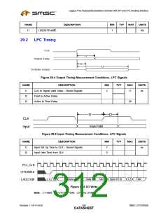
Figure 29.7 I/O Read
Note: L1=Start; L2=CYCTYP+DIR; L3=Sync of 0000
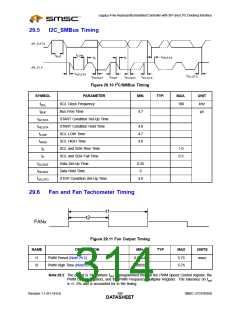
29.3
Serial IRQ Timing
PCI_CLK
SER_IRQ
t1
t2
Figure 29.8 Setup and Hold Time
DESCRIPTION
NAME
MIN
TYP
MAX
UNITS
nsec
t1
t2
SER_IRQ Setup Time to PCI_CLK Rising
SER_IRQ Hold Time to PCI_CLK Rising
7
0
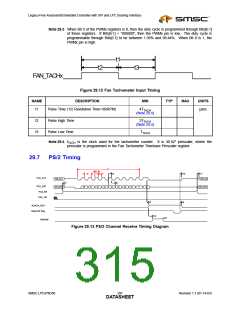
29.4
Serial Port Data Timing
Data
Stop (1-2 Bits)
Data (5-8 Bits)
Start
t1
Parity
TXD1, 2
Figure 29.9 Serial Port Data
MIN TYP
NAME
t1
DESCRIPTION
Serial Port Data Bit Time
MAX
UNITS
tBR (Note 29.1)
nsec
Note 29.1 tBR is 1/Baud Rate. The Baud Rate is programmed through the divisor latch registers. Baud
Rates have percentage errors indicated in the “Baud Rate” table in the “Serial Port” section.
SMSC LPC47N350
295
Revision 1.1 (01-14-03)
DATASHEET

 SMSC [ SMSC CORPORATION ]