ST7735
9
Function description
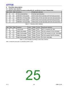
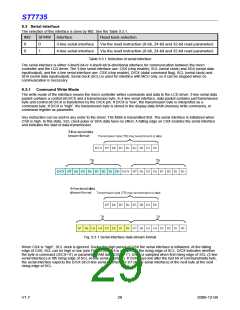
9.1 Interface type selection
The selection of given interfaces are done by setting IM2, IM1, and IM0 pins as shown in following table.
IM2 IM1 IM0 Interface
Read back selection
0
1
1
1
1
-
-
3-line serial interface
Via the read instruction
0
0
1
1
0
1
0
1
8080 MCU 8-bit parallel
8080 MCU 16-bit parallel
8080 MCU 9-bit parallel
8080 MCU 18-bit parallel
RDX strobe (8-bit read data and 8-bit read parameter)
RDX strobe (16-bit read data and 8-bit read parameter)
RDX strobe (9-bit read data and 8-bit read parameter)
RDX strobe (18-bit read data and 8-bit read parameter)
Table 9.1.1 Selection of MCU interface
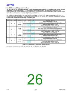
IM2 IM1 IM0 Interface
RDX
WRX
D/CX
Read back selection
0
1
1
1
1
-
-
3-line serial
Note1 Note1 SCL
D[17:1]: unused, D0: SDA
0
0
1
1
0
1
0
1
8080 8-bit parallel
RDX
WRX
WRX
WRX
WRX
D/CX
D/CX
D/CX
D/CX
D[17:8]: unused, D7-D0: 8-bit data
D[17:16]: unused, D15-D0: 16-bit data
D[17:9]: unused, D8-D0: 9-bit data
D17-D0: 18-bit data
8080 16-bit parallel RDX
8080 9-bit parallel RDX
8080 18-bit parallel RDX
Table 9.1.2 Pin connection according to various MCU interface
Note1: Unused pins can be open, or connected to DGND or VDDI.
V1.7
25
2009-12-04

 SITRONIX [ SITRONIX TECHNOLOGY CO., LTD. ]