C8051F52x-53x
5.3.4. Burst Mode
Burst Mode is a power saving feature that allows ADC0 to remain in a very low power state between con-
versions. When Burst Mode is enabled, ADC0 wakes from a very low power state, accumulates 1, 4, 8, or
16 samples using an internal Burst Mode clock (approximately 25 MHz), then re-enters a very low power
state. Since the Burst Mode clock is independent of the system clock, ADC0 can perform multiple conver-
sions then enter a very low power state within a single system clock cycle, even if the system clock is slow
(e.g. 32.768 kHz), or suspended.
Burst Mode is enabled by setting BURSTEN to logic 1. When in Burst Mode, AD0EN controls the ADC0
idle power state (i.e. the state ADC0 enters when not tracking or performing conversions). If AD0EN is set
to logic 0, ADC0 is powered down after each burst. If AD0EN is set to logic 1, ADC0 remains enabled after
each burst. On each convert start signal, ADC0 is awakened from its Idle Power State. If ADC0 is powered
down, it will automatically power up and wait the programmable Power-Up Time controlled by the
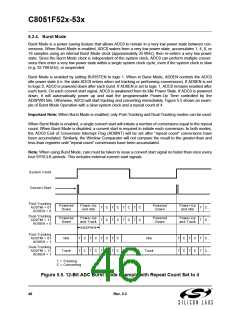
AD0PWR bits. Otherwise, ADC0 will start tracking and converting immediately. Figure 5.5 shows an exam-
ple of Burst Mode Operation with a slow system clock and a repeat count of 4.
Important Note: When Burst Mode is enabled, only Post-Tracking and Dual-Tracking modes can be used.
When Burst Mode is enabled, a single convert start will initiate a number of conversions equal to the repeat
count. When Burst Mode is disabled, a convert start is required to initiate each conversion. In both modes,
the ADC0 End of Conversion Interrupt Flag (AD0INT) will be set after “repeat count” conversions have
been accumulated. Similarly, the Window Comparator will not compare the result to the greater-than and
less-than registers until “repeat count” conversions have been accumulated.
Note: When using Burst Mode, care must be taken to issue a convert start signal no faster than once every
four SYSCLK periods. This includes external convert start signals.
System Clock
Convert Start
Post-Tracking
Powered
Down
Power-Up
and Idle
Powered
Down
Power-Up
and Idle
AD0TM = 01
AD0EN = 0
T
T
C
C
T
T
C
C
T
T
C
C
T
T
C
C
T
T
C..
C..
Dual-Tracking
AD0TM = 11
AD0EN = 0
Powered
Down
Power-Up
and Track
Powered
Down
Power-Up
and Track
AD0PW R
Post-Tracking
AD0TM = 01
AD0EN = 1
Idle
T
T
C
C
T
T
C
C
T
T
C
C
T
T
C
C
Idle
T
T
C
C
T
T
C
C
T
T
C..
C..
Dual-Tracking
AD0TM = 11
AD0EN = 1
Track
Track
T = Tracking
C = Converting
Figure 5.5. 12-Bit ADC Burst Mode Example with Repeat Count Set to 4
46
Rev. 0.3

 SILICON [ SILICON ]