C8051F52x-53x
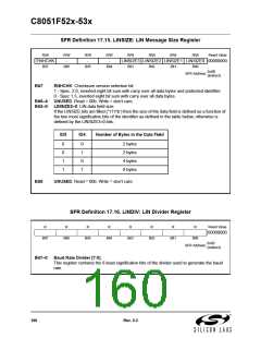
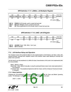
SFR Definition 17.17. LINMUL: LIN Multiplier Register
R/W
R/W
R/W
R/W
MUL3
Bit4
R/W
MUL2
Bit3
R/W
MUL1
Bit2
R/W
MUL0
Bit1
R/W
DIV
Bit0
Reset Value
PRESCL1 PRESCL0 MUL4
00000000
Bit7
Bit6
Bit5
0x0D
(indirect)
SFR Address:
Bit7–6: PRESCL1–0:Prescaler used to create the baud rate.
Bit5–1: MUL4–0: Multiplier used to create the baud rate.
Bit0:
DIV: Most significative bit of the divider used to create the baud rate.
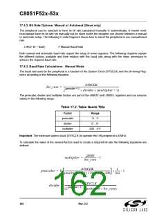
SFR Definition 17.18. LINID: LIN ID Register
R/W
R/W
Bit6
R/W
ID5
Bit5
R/W
ID4
Bit4
R/W
ID3
Bit3
R/W
ID2
Bit2
R/W
ID1
Bit1
R/W
ID0
Bit0
Reset Value
00000000
Bit7
0x0E
(indirect)
SFR Address:
Bit7–6: UNUSED. Read = 00b. Write = don’t care.
Bit5–0: ID5–0: Identifier
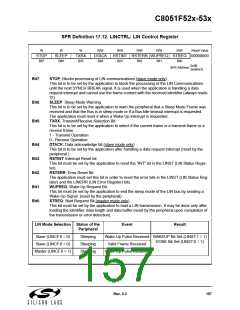
17.4. LIN Interface Setup and Operation
The Hardware based LIN peripheral allows for the implementation of both Master and Slave nodes with
minimal firmware overhead and complete control of the interface status while allowing for interrupt and
polled mode operation.
The first step to use the peripheral is to define the basic characteristics of the node to be implemented with
the microcontroller:
•Mode - Master or Slave
•Baud Rate - Either defined manually or using the autobaud feature (slave mode only) implemented in
the peripheral.
•Checksum Type - The peripheral implements both the Classic and the Enhanced Checksum formats
in Hardware.
17.4.1. Mode Definition
Following the LIN specification the peripheral implements in HW both the Slave and Master operating
modes. The following C-code fragment implements the master mode in the part:
LINCF |= 0x40;
// Master Mode Selected
Rev. 0.3
161

 SILICON [ SILICON ]