LC7218, 7218M, 7218JM
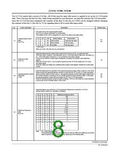
Xtal
3.6 MHz
Item
7.2 MHz
Time base clock
System clock
8 Hz
4 Hz
400 kHz
200 kHz
Frequency measurement period
Frequency measurement check signal
Reference frequencies
120/60 ms
240/120 ms
900 kHz
450 kHz
100, 50, 25, ......... 10, 9, 5, 1 kHz
50, 25, 12, 5, .......... 5, 4.5, 2.5, 0.5 kHz
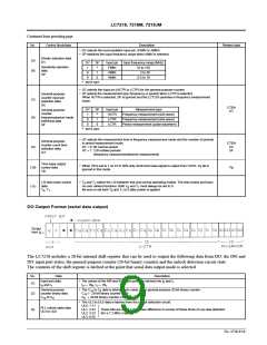
Serial data I/O (CL)
t
≥ 1.5 µs, t ≥ 1.5 µs
t ≥ 3.0 µs, t ≥ 3.0 µs
1 3
1
3
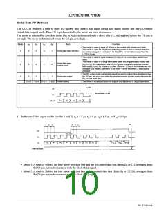
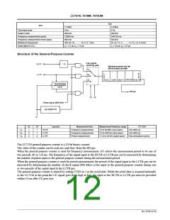
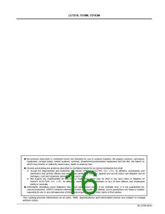
Structure of the General-Purpose Counter
SC
1
SF
*
Input pin
Measurement item
Frequency measurement
Frequency measurement
Period measurement
Measurement frequency range
10 to 60 MHz (sine wave)
15 to 500 kHz (sine wave)
1 Hz to 20 kHz (pulse wave)
GT (1/0)
120 m/60 ms
S
S
S
HCTR
LCTR
LCTR
1
2
3
0
1
120 m/60 ms
0
0
Two periods/one period
The LC7218 general-purpose counter is a 20-bit binary counter.
The value of the counter can be read out, msb first, from the DO pin.
When the general-purpose counter is used for frequency measurement, GT selects the measurement period to be one of
two periods, 60 or 120 ms. The frequency of the signal input to the HCTR or LCTR pin can be measured by determining
the number of pulses input to the general-purpose counter during the measurement period.
When the general-purpose counter is used for period measurement, the period of the signal input to the LCTR pin can be
measured by determining the number of check signal (900 kHz) cycles input to the general-purpose counter during one
or two periods of the signal input to the LCTR pin.
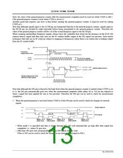
The general-purpose counter is started by setting CTEN to 1 in the serial data. While the serial data is acquired internally
in the LC7218 at the point the CE signal goes from high to low, the input to the HCTR or LCTR pin must be provided
within 10 ms after CE goes low.
No. 4758-12/16

 SANYO [ SANYO SEMICON DEVICE ]