LA76810A
Continued from preceding page.
Input signal
Symbol
Test point
15
Input signal
Test method
Bus bit/input signal
VS: 10000
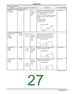
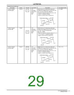
Vertical S-shaped
correction @16
VScor16
Y IN:
Monitor the pin 23 vertical ramp output and
measure the voltage at line 36, line 60, line 155,
line 179, line 274 and 298. Assign the
respective measured values to Va, Vb, Vc, Vd,
Ve and Vf. Calculate as follows:
Horizontal/
vertical sync
signal
PAL
VScor16 = 0.5((Vb-Va)+(Vf-Ve))/(Vd-Vc)
Line 298
Vertical ramp output
Line 179
Line 60
Line 274
Line 155
Line 36
Vertical S-shaped
correction @0
VScor0
Y IN:
Monitor the pin 23 vertical ramp output and
measure the voltage at the line 36, line 60, line
155, line 179, line 274 and line 298
Horizontal/
vertical sync
signal
with VSC = 00000.
23
PAL
Assign the respective measured values to Va, Vb,
Vc, Vd, Ve and Vf. Calculate as follows:
VScor0 = 0.5((Vb-Va)+(Vf-Ve))/(Vd-Vc)
Line 298
Vertical ramp output
Line 179
Line 60
Line 274
Line 155
Line 36
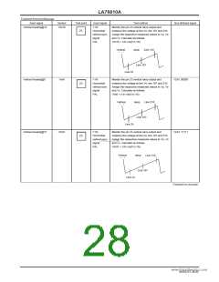
Vertical S-shaped
correction @31
VScor31
Y IN:
Monitor the pin 23 vertical ramp output and
measure the voltage at line 36, line 60, line 155,
VSC: 11111
Horizownwtawl.D/ ataSheet4U.com
23
vertical sync
signal
PAL
line 179, line 274 and 298. Assign the
respective measured values to Va, Vb, Vc, Vd,
Ve and Vf. Calculate as follows:
VScor16 = 0.5((Vb-Va)+(Vf-Ve))/(Vd-Vc)
Line 298
Vertical ramp output
Line 179
Line 60
Line 274
Line 155
Line 36
NoA0252-29/40

 SANYO [ SANYO SEMICON DEVICE ]