LA76810A
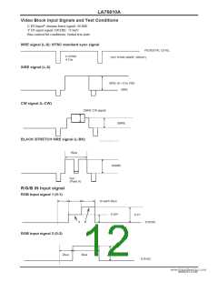
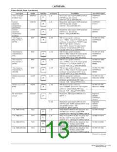
Video Block Test Conditions
Input signal
Symbol
Test point
21
Input signal
Test method
Bus bit/input signal
Video overall gain
(Contrast max)
CONT127
L-50
Measure the output signal’s 50IRE amplitude
(CNTHB Vp-p) and calculate
CONTRAST:
1111111
CONT127 = 20Log (CNTHB/0.357).
Measure the output signal’s 50IRE amplitude
(CNTCB Vp-p) and calculate
Contrast
CONT63
CONT0
BW1
L-50
CONTRAST:
0111111
21
21
21
adjustment
characteristics
(normal/max)
Contrast
adjustment
characteristics
(min/max)
Video frequency
Characteristics 1
(SVHS)
CONT63 = 20Log (CNTCB/0.357).
L-50
Measure the output signal’s 50IRE amplitude
(CNTLB Vp-p) and calculate
CONT0 = 20Log (CNTLB/0.357).
CONTRAST:
0000000
L-CW
With the input signal’s continuous
FILTER SYS: 0100
SHARPNESS:
000000
wave = 100kHz, measure the output signal’s
continuous wave amplitude (PEAKDC Vp-p).
With the input signal’s continuous
wave = 6MHz, measure the output signal’s
continuous wave amplitude (CW7 Vp-p).
Calculate BW1 = 20Log (CW6/PEAKDC).
With the input signal’s continuous
wave = 3.2MHz, measure the output signal’s
continuous wave amplitude (CW3.2 Vp-p).
Calculate BW2 = 20Log (CW3.2/PEAKDC).
With the input signal’s continuous
wave = 2.6MHz, measure the output signal’s
continuous wave amplitude (CW2.6 Vp-p).
Calculate BW3 = 20Log (CW2.6/PEAKDC).
With the input signal’s continuous
wave = 3.1MHz, measure the output signal’s
continuous wave amplitude (CW3.1 Vp-p).
Calculate BW4 = 20Log (CW3.1/PEAKDC).
Video frequency
Characteristics 2
(PAL)
BW2
BW3
L-CW
L-CW
L-CW
L-CW
FILTER SYS: 0010
SHARPNESS:
000000
21
21
21
21
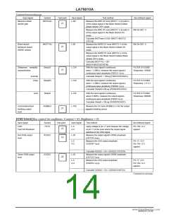
Video frequency
Characteristics 3
(NTSC)
FILTER SYS: 0000
SHARPNESS:
000000
Video frequency
Characteristics 4
(SECAM)
BW4
FILTER SYS: 1000
SHARPNESS:
000000
www.DataSheet4U.com
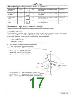
Chroma trap amount
PAL
CtraPP
With the input signal’s continuous
FILTER SYS: 010
Sharpness: 000000
wave = 4.43MHz, measure the output signal’s
continuous wave amplitude (F0P Vp-p).
Calculate CtraP = 20Log (F0P/PEAKDC).
Chroma trap amount
NTSC
CtraPN
L-CW
With the input signal’s continuous
FILTER SYS: 000
Sharpness: 000000
21
21
wave = 3.58MHz, measure the output signal’s
continuous wave amplitude (F0N Vp-p).
Calculate CtraN = 20Log (F0N/PEAKDC).
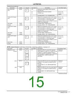
DC transmission
amount
ClampG1
L-0
Measure the output signal’s 0IRE DC level
(BRTPL V).
Brightness:
0000000
CONTRAST:
1111111
L-100
Measure the output signal’s 0IRE DC level
(DRVPH V) and 100IRE amplitude (DRVH Vp-p)
and calculate ClampG = 100 ×
Brightness:
0000000
Contrast:
(1+(DRVPH - BRTPL)/DRVH).
1111111
Y-DL TIME1(SVHS)
Y-DL TIME2(PAL)
TdY1
TdY2
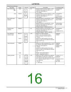
TdY3
TdY4
L-50
L-50
L-50
L-50
Obtain the time difference (the delay time) from
when the rise of the input signal's 50IRE
amplitude to the output signal's 50IRE amplitude.
Obtain the time difference (the delay time) from
when the rise of the input signal's 50IRE
amplitude to the output signal's 50IRE amplitude.
Obtain the time difference (the delay time) from
when the rise of the input signal's 50IRE
amplitude to the output signal's 50IRE amplitude.
Obtain the time difference (the delay time) from
when the rise of the input signal's 50IRE
amplitude to the output signal's 50IRE amplitude.
FILTER SYS:0100
21
21
21
21
FILTER SYS:0010
FILTER SYS:0000
FILTER SYS:1000
Continued on next page.
Y-DL TIME3(NTSC)
Y-DL TIME4(SECAM)
NoA0252-13/40

 SANYO [ SANYO SEMICON DEVICE ]