LA76810A
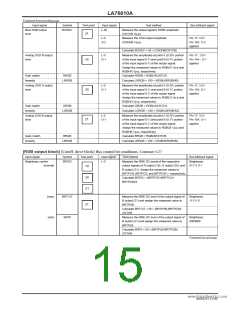
Continued from preceding page.
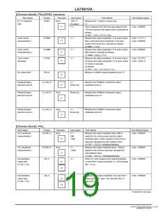
Input signal
Symbol
BOSDC
Test point
21
Input signal
Test method
Bus bit/input signal
Blue RGB output
level
L-50
Measure the output signal’s 50IRE amplitude
(CNTCB Vp-p).
L-0
O-2
Measure the OSD output amplitude
(OSDHB Vp-p).
Pin 17: 3.5V
Pin 16A: O-2
applied
Calculate BOSDC = 50 × (OSDHB/CNTCB)
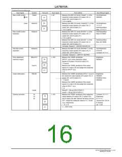
Analog OSD R output
level
L-0
O-1
Measure the amplitudes at point A (0.35V portion
of the input signal 0-1) and point B (0.7V portion
of the input signal 0-1) of the output signal.
Assign the measured values to RGBLR Vp-p and
RGBHR Vp-p, respectively.
Pin 17 : 3.5V
Pin 14A : O-1
applied
19
20
21
Gain match
linearity
RRGB
Calculate RRGB = RGBLR/CNTCR.
LRRGB
Calculate LRRGB = 100 × (RGBLR/RGBHR).
Analog OSD G output
level
L-0
O-1
Measure the amplitudes at point A (0.35V portion
of the input signal 0-1) and point B (0.7V portion
of the input signal 0-1) of the output signal.
Assign the measured values to RGBLG Vp-p and
RGBHG Vp-p, respectively.
Pin 17: 3.5V
Pin 15A: O-1
applied
Gain match
linearity
GRGB
Calculate GRGB = RGBLG/CNTCG.
LGRGB
Calculate LGRGB = 100 × (RGBLG/RGBHG).
Analog OSD B output
level
L-0
O-1
Measure the amplitudes at point A (0.35V portion
of the input signal 0-1) and point B (0.7V portion
of the input signal 0-1) of the output signal.
Assign the measured values to RGBLB Vp-p and
RGBHB Vp-p, respectively.
Pin 17: 3.5V
Pin 16A: O-1
applied
Gain・match
BRGB
Calculate BRGB = RGBLB/CNTCB.
linearity
LBRGB
Calculate LBRGB = 100 × (RGBLB/RGBHB).
.
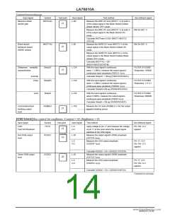
[RGB output block] (Cutoff, drive block) Bus control bit conditions: Contrast=127
Input signal
Symbol
BRT63
Test point
Input swigwnwa.DlataSheet4U.com
Test method
Bus bit/input signal
Brightness control
L-0
Measure the 0IRE DC levels of the respective
output signals of R output (19), G output (20), and
B output (21). Assign the measured values to
BRTPCR, BRTPCG, and BRTPCB V, respectively.
Calculate BRT63 = (BRTPCR+BRTPCG+
BRTPCB)/3.
Brightness:
01111111
(normal)
19
20
21
(max)
(min)
BRT127
BRT0
Measure the 0IRE DC level of the output signal of
B output (21) and assign the measured value to
BRTPHB.
Calculate BRT127 = 50 × (BRTPHB-BRTPCB)/
CNTHB.
Measure the 0IRE DC level of the output signal of
B output (21) and assign the measured value to
BRTPLB.
Brightness:
1111111
21
Brightness:
0000000
Calculate BRT0 = 50 × (BRTPLB-BRTPCB)/
CNTHB.
Continued on next page.
NoA0252-15/40

 SANYO [ SANYO SEMICON DEVICE ]