LA76810A
Continued from preceding page.
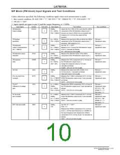
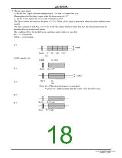
Input signal
Symbol
Test point
21
Input signal
L-BK
Test method
Bus bit/input signal
Blk Str DEF: 0
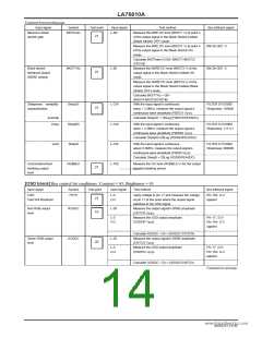
Maximum black
stretch gain
BKSTmax
Measure the 0IRE DC level (BKST1 V) at point A
of the output signal in the Black Stretch Defeat
(Black Stretch OFF) mode.
Measure the 0IRE DC level (BKST2 V) at point A
of the output signal in the Black Stretch ON
mode.
Calculate BKSTmax=2×50× (BKST1-BKST2)
/CNTHB.
Black stretch
threshold ∆black
(60IRE ∆black)
BKSTTH∆
L-60
Measure the 60IRE DC level (BKST3 V) of the
output signal in the Black Stretch Defeat ON
mode.
Measure the 60IRE DC level (BKST4 V) of the
output signal in the Black Stretch Defeat (Black
Stretch OFF) mode.
Calculate BKSTTH∆ = 50×
(BKST4-BKST3)/CNTHB.
With the input signal’s continuous
wave = 2.2MHz, measure the output signal’s
continuous wave amplitude (F00S31 Vp-p).
Calculate Sharp31 = 20Log (F00S31/PEAKDC).
Blk Str DEF: 0
21
21
Sharpness variability
characteristics
Sharp31
Sharp63
Sharp0
L-CW
L-CW
L-CW
L-100
FILTER SYS:0000
Sharpness: 100000
(normal)
(max)
With the input signal’s continuous
FILTER SYS:0000
Sharpness: 111111
wave = 2.2MHz, measure the output signal’s
continuous wave amplitude (F00S63 Vp-p).
Calculate Sharp63=20Log (F00S63/PEAKDC).
(min)
With the input signal’s continuous
FILTER SYS:0000
Sharpness: 000000
wave=2.2MHz, measure the output signal’s
continuous wave amplitude (F00S0 Vp-p).
Calculate Sharp0 = 20Log (F00S0/PEAKDC).
Horizontal/vertical
blanking output
level
RGBBLK
Measure the DC level (RGBBLK V) for the output
signal’s blanking period.
21
www.DataSheet4U.com
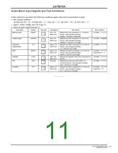
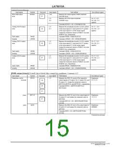
[OSD block] Bus control bit conditions: Contrast = 63, Brightness = 63
Input signal
Symbol
FSTH
Test point
Input signal
Test method
Bus bit/input signal
OSD
Fast SW threshold
L-0
O-2
Apply voltage to pin 17 and measure the voltage
at pin 17 at the point where the output signal
switches to the OSD signal.
Pin 16A: O-2
applied
21
Red RGB output
level
ROSDC
GOSDC
L-50
Measure the output signal’s 50IRE amplitude
(CNTCR Vp-p).
Measure the OSD output amplitude
(OSDHR Vp-p).
19
20
L-0
O-2
Pin 17: 3.5V
Pin 14A: O-2
applied
Calculate ROSDC = 50 × (ROSDC /CNTCR)
Measure the output signal’s 50IRE amplitude
(CNTCG Vp-p).
Green RGB output
level
L-50
L-0
O-2
Measure the OSD output amplitude
(OSDHG Vp-p).
Pin 17: 3.5V
Pin 15A: O-2
applied
Calculate GOSDC = 50 × (GOSDC/CNTCG)
Continued on next page.
NoA0252-14/40

 SANYO [ SANYO SEMICON DEVICE ]