LA76810A
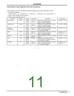
Audio Block Input Signals and Test Conditions
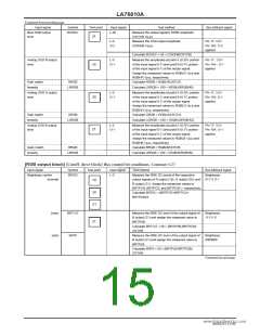
Unless otherwise specified, the following conditions apply when each measurement is made.
1. Bus control condition:
AUDIO.MUTE = "0", AUDIO.SW = "1", VOL.FIL = "0", SIF.SYS = "01", IF.AGC.SW = "1"
2. Input 5.5MHz, 90dBµ and CW at pin 54.
3. Enter an input signal from pin 51.
Input signal
Symbol
AGMAX
Test point
Input signal
Test method
Bus conditions
Maximum gain
1kHz, CW
500mVrms
Measure the 1kHz component (V1: mVrms) at
the pin 1 and calculate as follows:
AGMAX = 20*LOG (V1/500) [dB]
VOLUME = "1111111"
1
Variable range
ARANGE
AF
1kHz, CW
500mVrms
Measure the 1kHz component (V2: mVrms) at
the pin 1 and calculate as follows:
ARANGE = 20*LOG (V1/V2) [dB]
Measure the 20kHz component (V3: mVrms) at
the pin 1 and calculate as follows:
AF = 20*LOG (V3/V1) [dB]
Measure the 20kHz component (V4: mVrms) at
the pin 1 and calculate as follows:
AMUTE = 20*LOG (V3/V4) [dB]
VOLUME = "0000000"
VOLUME = "1111111"
1
1
1
Frequency
characteristics
20kHz, CW
500mVrms
Mute
AMUTE
20kHz, CW
500mVrms
VOLUME = "1111111"
AUDIO.MUTE = ”1”
Distortion
S/N
ATHD
ASN
1kHz, CW
500mVrms
No signal
Measure the distortion of the 1kHz component at
the pin 1.
Measure the noise level (DIN AUDIO, V5:
mVrms) at the pin 1 and calculate as follows:
ASN = 20*LOG (V1/V5) [dB]
VOLUME = "1111111"
VOLUME = "1111111"
1
1
Crosstalk
ACT
20kHz, CW
500mVrms
Measure the 20kHz component (V6: mVrms) at
the pin 1 and calculate as follows:
ACT = 20*LOG (V3/V6) [dB]
VOLUME = "1111111"
AUDIO.SW = "0"
1
www.DataSheet4U.com
NoA0252-11/40

 SANYO [ SANYO SEMICON DEVICE ]