LA76810A
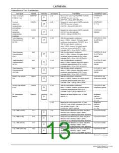
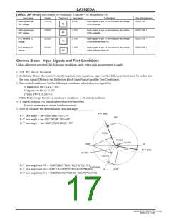
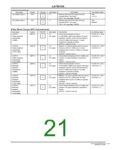
[VIDEO SW block] Bus control bit conditions: Contrast = 63, Brightness = 63
Input signal
Symbol
Test point
Input signal
Test method
Bus bit/input signal
VIDEO SW: 1
Video signal input
1DC voltage
VIN1DC
L-100
Input signals to pin 42 and measure the voltage
of the pedestal.
42
Video signal input
2DC voltage
VIN2DC
SVODC
SVOAC
L-100
L-100
L-100
Input signals to pin 44 and measure the voltage
of the pedestal.
VIDEO SW: 0
VIDEO SW: 1
VIDE0 SW: 1
44
40
SVO terminal DC
voltage
Input signals to pin 42 and measure the voltage
of the pedestal at pin 40.
SVO terminal AC
voltage
Input signals to pin 42 and measure the voltage
of the pedestal at pin 40.
40
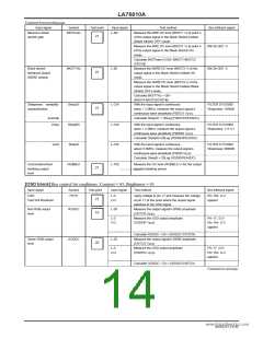
Chroma Block Input Signals and Test Conditions
Unless otherwise specified, the following conditions apply when each measurement is made.
1. VIF, SIF blocks: No signal
2. Deflection Block: Horizontal/vertical composite sync signals are input and the deflection block must be locked into
the sync signals (Refer to the Deflection Block Input Signals and the Test Conditions).
3. Bus control conditions: Set the following conditions unless otherwise specified.
Y Input is 42 Pin (EXT-V IN),
C Input is 44 Pin (S-C IN)
(Video SW=1, C.Ext=1)
Other DAC except the above-mentioned conditions is all initial conditions.
4. Y Input condition: No signal unless otherwise specified.
(Sync is necessary to obtain synchronization).
5. How to calculate the demodulation ratio and angle:
www.DataSheet4U.com
R-Y axis
B-Y axis angle = tan-1(B(0)/B(270))+270°
90°
R-Y axis angle = tan-1(R(180)/R( 90))+90°
G-Y axis angle = tan-1(G(270)/G(180))+180°
R(90)
R(180)
B(270)
180°
0°
B(0)
B-Y axis
G(180)
G(270)
B-Y axis amplitude Vb = SQRT(B(0)*B(0)+B(270)*B(270))
G-Y axis
R-Y axis amplitude Vr = SQRT(R(180)*R(180)+R(90)*R(90))
G-Y axis amplitude Vg = SQRT(G(180)*G(180)+G(270)*G(270))
270°
NoA0252-17/40

 SANYO [ SANYO SEMICON DEVICE ]