LA76810A
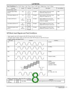
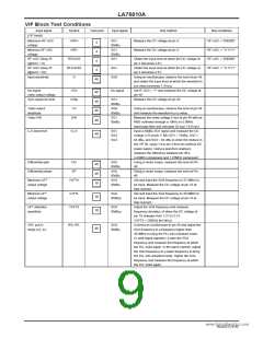
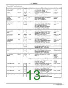
VIF Block Test Conditions
Input signal
Symbol
Test point
Input signal
Test method
Bus conditions
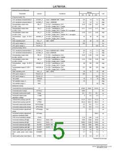
[VIF block]
Maximum RF AGC
voltage
Minimum RF AGC
voltage
RF AGC Delay Pt
(@DAC = 0)
RF AGC Delay Pt
(@DAC = 63)
Input sensitivity
VRFH
VRFL
SG1
80dBµ
SG1
80dBµ
SG1
Measure the DC voltage at pin 4.
Measure the DC voltage at pin 4.
RF.AGC = "000000"
RF.AGC = "111111"
RF.AGC = "000000"
RF.AGC = "111111"
4
4
RFAGC0
RFAGC63
Vi
Obtain the input level at which the DC voltage at
pin 4 becomes 4.5V.
Obtain the input level at which the DC voltage at
pin 4 becomes 4.5V.
Using an oscilloscope, observe the level at pin 46
and obtain the input level at which the waveform's
p-p value becomes 1.4Vp-p.
4
4
SG1
SG6
46
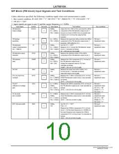
No-signal
video output voltage
Sync signal tip level
VOn
VOtip
VO
No signal
Set IF AGC = “1” and measure the DC voltage at
pin 46.
Measure the DC voltage at pin 46.
46
46
46
46
SG1
80dBµ
SG6
80dBµ
SG1
80dBµ
Video output
amplitude
Video S/N
Using an oscilloscope, observe the level at pin 46
and measure the waveform’s p-p value.
Measure the noise voltage (Vsn) at pin 46 with an
RMS voltmeter through a 10kHz to 5.0MHz
band-pass filter and calculate 20 log (1.43/Vsn).
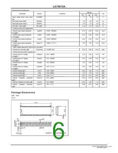
Input a 80dBµ SG1 signal and measure the DC
voltage (V3) at pin 3. Mix SG1 = 74dBµ, SG2 =
64 dBµ, and SG3 = 64 dBµ to enter the mixture in
the VIF IN. Apply V3 to pin 3 from an external DC
power supply. Using a spectrum analyzer,
measure the difference between pin 46’s
4.43MHz component and 1.07MHz component.
Using a vector scope, measure the level at Pin
46.
S/N
C-S beat level
IC-S
SG1
SG2
SG3
46
Differential gain
DG
DP
SG5
80dBµ
46
46
10
Differential phase
SG5 www.DataSheUet4sUin.cgoma vector scope, measure the level at Pin
80dBµ
SG4
80dBµ
46.
Maximum AFT
output voltage
VAFTH
Set and input the SG4 frequency to 37.9MHz to
be input. Measure the DC voltage at pin 10 at
that moment.
Minimum AFT
output voltage
VAFTL
VAFTS
SG4
80dBµz
Set and input the SG4 frequency to 39.9MHz to
be input. Measure the DC voltage at pin 10 at
that moment.
Adjust the SG4 frequency and measure
frequency deviation ∆f when the DC voltage at
pin 10 changes from 1.5V to 3.5V.
10
10
AFT detection
sensitivity
SG4
80dBµz
VAFTS = 2000/∆f [mV/kHz]
APC pull-in
range (U), (L)
fPU, fPL
SG4
80dBµ
Connect an oscilloscope to pin 46 and adjust the
SG4 frequency to a frequency higher than
38.9MHz to bring the PLL into unlocked mode.
(A beat signal appears.) Lower the SG4
frequency and measure the frequency at which
the PLL locks again. In the same manner, adjust
the SG4 frequency to a lower frequency to bring
the PLL into unlocked mode. Higher the SG4
frequency and measure the frequency at which
the PLL locks again.
46
NoA0252-9/40

 SANYO [ SANYO SEMICON DEVICE ]