LA76810A
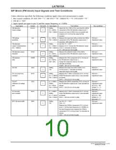
SIF Block (FM block) Input Signals and Test Conditions
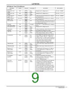
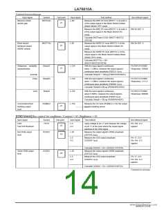
Unless otherwise specified, the following conditions apply when each measurement is made.
1. Bus control condition: IF.AGC.SW = "1", SIF.SYS = "01", DEEM-TC = "0", FM.GAIN = "0"
2. SW:IF1 = "ON"
3. Input signals are input to pin 54 and the carrier frequency is 5.5MHz.
Input signal
Symbol
SOADJ
Test point
Input signal
Test method
Bus conditions
FM detection
output voltage
90dBµ,
fm = 400Hz,
Adjust the DAC (FM.LEVEL) such that the 400Hz
component of the FM detection output at pin 2
2
FM = ±30kHz become as close to 600mVrms as possible and
measure (SV1:mVrms) the output at that
moment.
FM limiting
sensitivity
SLS
SF
fm = 400Hz,
Measure the input level (dBµ) at which the 400Hz
FM level =
Adjustment value
2
2
FM = ±30kHz component of the FM detection output at pin 2
becomes -3dB relative to SV1.
Set SW: IF1 = "OFF".
Measure (SV2: mVrms) the FM detection output
FM detection
output f characteristics
(fm = 100kHz)
90dBµ,
fm = 100kHz
FM = ±30kHz of pin 2. Calculate as follows:
FM level =
Adjustment value
SF = 20*LOG (SV1/SV2) [dB]
FM detection output
distortion
STHD
SAMR
90dBµ,
Measure the distortion factor of the 400Hz
component of the FM detection output at pin 2.
FM level =
Adjustment value
2
2
fm = 400Hz,
FM = ±30kHz
90dBµ,
fm = 400Hz,
AM = 30%
AM rejection
ratio
Measure the 1kHz component (SV3: mVrms) of
the FM detection output at pin 2.
Assign the measured value to SV3 and
calculate as follows:
FM level =
Adjustment value
SAMR = 20*LOG (SV1/SV3) [dB]
SIF.S/N
SSN
90dBµ,
CW
Measure the noise level (DIN AUDIO, SV4:
mVrms) at pin 2. Calculate as follows:
SSN=20*LOG(SV1/SV4) [dB]
Measure the 3.18kHz component (SV5: mVrms)
of the FM detection output at pin 2 and calculate
FM level =
Adjustment value
2
2
PAL de-emph time
constant
SPTC
90dBµ,
FM level =
Adjustment value
fm = 3w.1w8wK.DHatzaSheet4U.com
FM = ±30KHz as follows:
SNTC = 20*LOG (SV1/SV5) [dB]
PAL/NT
Difference of voltage
gain
SGD
SNTC
SBW
fo = 4.5MHz
90dBµ,
fm = 400Hz
Measure the 400Hz component (SV6: mVrms) of
the FM detection output at pin 2 and calculate as
follows:
FM level =
2
2
2
Adjustment value
SIF.SYS = "00"
DEEM-TC = "1"
FM.GAIN = "1"
FM level =
Adjustment value
SIF.SYS = "00"
DEEM-TC = "1"
FM.GAIN = "1"
FM level=
FM = ±15KHz SNTC = 20*LOG (SV1/SV6) [dB]
NT de-emph
time constant
fo = 4.5MHz
90dBµ,
Measure the 2.12kHz component (SV7: mVrms)
of the FM detection output at pin 2 and calculate
fm = 2.12kHz as follows:
FM = ±15kHz SNTC = 20*LOG (SV6/SV7) [dB]
BPF 3db band width
90dBµ,
CW
Set SW: IF1 = "OFF".
Pin9 = 5V
Adjustment value
Measure the 458kHz component (SV8: mVrms)
at pin 2. Set the input frequency to 5.565MHz to
the input frequency and measure the 393kHz
component (SV9: mVrms) at pin 2 to calculate as
follows:
SBW = 20*LOG (SV8/SV9) [dB]
NoA0252-10/40

 SANYO [ SANYO SEMICON DEVICE ]