LA76810A
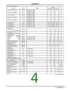
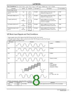
Test Conditions Ta = 25°C, V
= V = V = V = 5.0V, l = 19mA, I
= l = 27mA
CC 25
CC
8
31
43
18
Parameter
Symbol
Test point
Input signal
Test method
Bus conditions
Initial
[Circuit voltage, current]
Horizontal supply voltage
(pin 25)
V
V
No signal
No signal
No signal
Apply a current of 27mA to pin 25 and
measure the voltage at pin 25.
25
18
25
18
RGB supply voltage (pin 18)
IF supply current (pin 8)
Apply a current of 19mA to pin 18 and
measure the voltage at pin 18.
Initial
Initial
I
Apply a voltage of 5.0V to pin 8 and
measure the incoming DC current (mA).
(IF AGC 2.5V applied)
8
(CDDI
)
)
CC
8
CCD supply current (pin 31)
I
No signal
No signal
Apply a voltage of 5.0V to pin 31 and
measure the incoming DC current (mA).
Initial
Initial
31
(CCDI
31
43
CC
Video/vertical supply current
(pin 43)
I
Apply a voltage of 5.0V to pin 43 and
measure the incoming DC current (mA).
43
(DEFI
)
CC
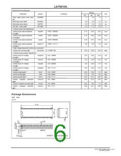
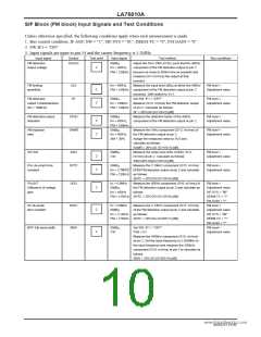
VIF Block Input Signals and Test Conditions
1. Input signals must all be input to the PIF IN (pin 6) in the Test Circuit.
2. All input signal voltage values are the levels at the VIF IN (pin 6) in the Test Circuit.
3. Signal contents and signal levels
Input signal
Waveform
Conditions
SG1
38.9MHz
34.47MHz
33.4MHz
CW
CW
CW
CW
www.DataSheet4U.com
SG2
SG3
SG4
SG5
Frequency variable
38.9MHz
87.5% Video Mod.
10-stairstep wave
(Subcarrier: 4.43MHz)
SG6
38.9MHz
fm = 15kHz, AM = 78%
4. Before measurement, adjust the DAC as follows.
Parameter
Video
Level DAC
Test point
Input signal
Adjustment
SG6, 80dBµ
Set the output level at pin 46 as close to 2.0Vp-p as possible.
46
NoA0252-8/40

 SANYO [ SANYO SEMICON DEVICE ]