S3C4510B
HDLC CONTROLLERS
31 30 29 28 27 26 25 24 23 22 21 20 19 18 17 16 15 14 13 12 11 10 9
8
7
6
5
4
3 2 1 0
D D D D D D D D R D
R R R R R R R R R R
R
x
F
A
T
x
F
A
T T T
T
x
F
C
R
x
R
B
P P T T T R R R x
T
x
x
x
x
x
x
x
I
x x x x
x
x x
L L
x
x
x
x
x
x
I
M O N C A
F S D F
U S C
C T
T S
S
L L N N F N N F E A
T O O L D O L D R B
O V O R B D V D C D
V
C T L
C D
D
M M
R T
E
E
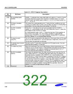
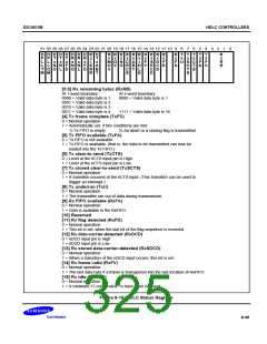
[3:0] Rx remaining bytes (RxRB)
At 1-word boundary:
At 4-word boundary:
0000 = Valid data byte is 1
0001 = Valid data byte is 2
0010 = Valid data byte is 3
0011 = Valid data byte is 4
0000 = Valid data byte is 1
.
.
1111 = Valid data byte is 16
[4] Tx frame complete (TxFC)
0 = Normal operation
1 = Automatically set; if two conditions are met:
1) Tx FIFO is empty.
2) An abort or a closing flag is transmitted.
[5] Tx FIFO available (TxFA)
0 = Tx FIFO is not available.
1 = Tx FIFO is available. (that is, the data to be transmitted can now be
loaded into the Tx FIFO.)
[6] Tx clear-to send (TxCTS)
0 = Level at the nCTS input pin is High.
1 = Level at the nCTS input pin is Low.
[7] Tx stored clear-to-send (TxSCTS)
0 = Normal operation
1 = A transition occured at the nCTS input. (This transition can be used to
trigger an interrupt.)
[8] Tx underrun (TxU)
0 = Normal operation
1 = The transmitter ran out of data during transmission.
[9] Rx FIFO available (RxFA)
0 = Normal operation
1 = Data is available in the RxFIFO.
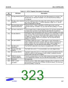
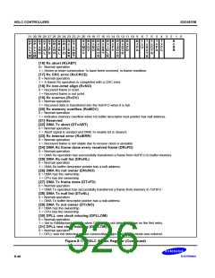
[10] Reserved
[11] Rx flag detected (RxFD)
0 = Normal operation
1 = This bit is set, when the last bit of the flag sequence is received.
[12] Rx data-carrier-detected (RxDCD)
0 = nDCD input pin is High
1 = nDCD input pin is Low
[13] Rx stored data-carrier-detected (RxSDCD)
0 = Normal operation
1 = When a transition of the nDCD input occurs, this bit is set.
[14] Rx frame valid (RxFV)
0 = Normal operation
1 = The last data byte if a frame is transgerred into the last location of RxFIFO.
[15] Rx idle (RxIDLE)
0 = Normal operation
1 = A minimum 15 consecutive 1s have been reveived.
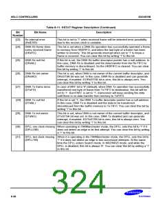
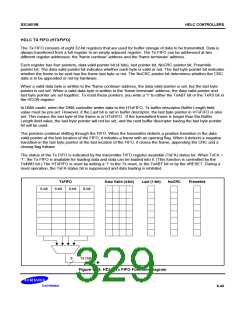
Figure 8-16. HDLC Status Register
8-39

 SAMSUNG [ SAMSUNG ]