R8C/13 Group
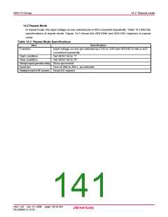
14.6 Inflow Current Bypass Circuit
14.6 Inflow Current Bypass Circuit
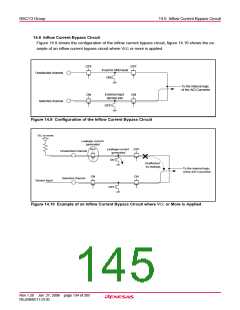
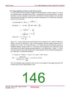
Figure 14.9 shows the configuration of the inflow current bypass circuit, figure 14.10 shows the ex-
ample of an inflow current bypass circuit where VCC or more is applied.
OFF
OFF
Fixed to GND level
ON
Unselected channel
To the internal logic
of the A/D Converter
External input
latched into
ON
ON
Selected channel
OFF
Figure 14.9 Configuration of the Inflow Current Bypass Circuit
VCC or more
Leakage current
generated
Leakage current
generated
OFF
OFF
Unselected channel
ON
Unaffected
by leakage
To the internal logic
of the A/D Converter
ON
ON
Selected channel
Sensor input
OFF
Figure 14.10 Example of an Inflow Current Bypass Circuit where VCC or More is Applied
Rev.1.20 Jan 27, 2006 page 134 of 205
REJ09B0111-0120

 RENESAS [ RENESAS TECHNOLOGY CORP ]