R8C/13 Group
14.3 Sample and Hold mode/14.4 A/D conversion cycles
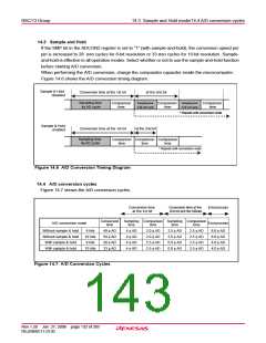
14.3 Sample and Hold
If the SMP bit in the ADCON2 register is set to “1” (with sample-and-hold), the conversion speed per
pin is increased to 28 ØAD cycles for 8-bit resolution or 33 ØAD cycles for 10-bit resolution. Sample-
and-hold is effective in all operation modes. Select whether or not to use the sample-and-hold function
before starting A/D conversion.
When performing the A/D conversion, charge the comparator capacitor inside the microcomputer.
Figure 14.6 shows the A/D conversion timing diagram.
Sample & Hold
Conversion time at the 1st bit
at the 2nd bit
disabled
Sampling time
4φ AD cycle
Sampling time
2.5 AD cycle
Sampling time
2.5 AD cycle
Comparison
time
Comparison
time
Comparison
time
φ
φ
* Repeat until conversion ends
Sample & Hold
enabled
Conversion time at the 1st bit
at the 2nd bit
Sampling time
4φ AD cycle
Comparison Comparison Comparison
time time time
* Repeat until conversion ends
Figure 14.6 A/D Conversion Timing Diagram
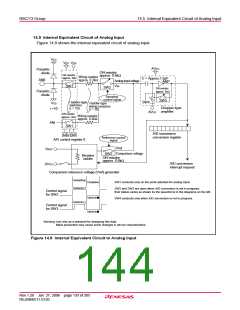
14.4 A/D conversion cycles
Figure 14.7 shows the A/D conversion cycles.
Conversion time
at the 1st bit
Conversion time at the
2nd bit and the follows
End process
End process
Conversion Sampling Comparison Sampling Comparison
A/D conversion mode
time
time
time
time
time
Without sample & hold
Without sample & hold
With sample & hold
With sample & hold
8 bits
49 φ AD
59 φ AD
28 φ AD
33 φ AD
4 φ AD
4 φ AD
4 φ AD
4 φ AD
2.0 φ AD
2.0 φ AD
2.5 φ AD
2.5 φ AD
2.5 φ AD
2.5 φ AD
0.0 φ AD
0.0 φ AD
2.5 φ AD
2.5 φ AD
2.5 φ AD
2.5 φ AD
8.0 φ AD
8.0 φ AD
4.0 φ AD
4.0 φ AD
10 bits
8 bits
10 bits
Figure 14.7 A/D Conversion Cycles
Rev.1.20 Jan 27, 2006 page 132 of 205
REJ09B0111-0120

 RENESAS [ RENESAS TECHNOLOGY CORP ]