M51995AP/AFP
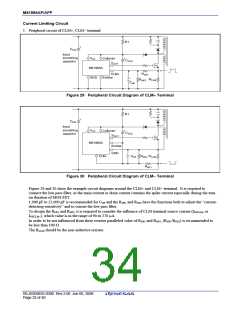
2. Over current limiting curve
(1) In case of feed forward system
I2
IP1
I1
IP2
CLM
I2
RCLM
I1
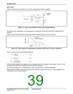
(b) Primary and secondary current
(a) Feed forward system
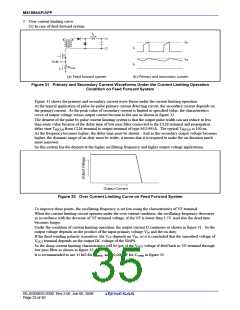
Figure 31 Primary and Secondary Current Waveforms Under the Current Limiting Operation
Condition on Feed Forward System
Figure 31 shows the primary and secondary current wave-forms under the current limiting operation.
At the typical application of pulse-by-pulse primary current detecting circuit, the secondary current depends on
the primary current. As the peak value of secondary current is limited to specified value, the characteristics
curve of output voltage versus output current become to the one as shown in figure 32.
The demerit of the pulse by pulse current limiting system is that the output pulse width can not reduce to less
than some value because of the delay time of low pass filter connected to the CLM terminal and propagation
delay time TPDCLM from CLM terminal to output terminal of type M51995A. The typical TPDCLM is 100 ns.
As the frequency becomes higher, the delay time must be shorter. And as the secondary output voltage becomes
higher, the dynamic range of on-duty must be wider; it means that it is required to make the on-duration much
more narrower.
So this system has the demerit at the higher oscillating frequency and higher output voltage applications.
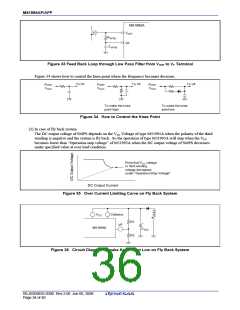
Output Current
Figure 32 Over Current Limiting Curve on Feed Forward System
To improve these points, the oscillating frequency is set low using the characteristics of VF terminal.
When the current limiting circuit operates under the over current condition, the oscillating frequency decreases
in accordance with the decrease of VF terminal voltage, if the VF is lower than 3.5V.And also the dead time
becomes longer.
Under the condition of current limiting operation, the output current I2 continues as shown in figure 31. So the
output voltage depends on the product of the input primary voltage VIN and the on-duty.
If the third winding polarity is positive, the VCC depends on VIN, so it is concluded that the smoothed voltage of
V
OUT terminal depends on the output DC voltage of the SMPS.
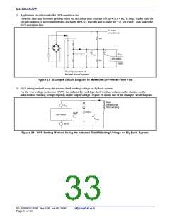
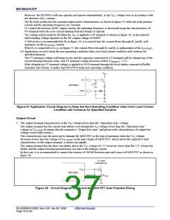
So the sharp current limiting characteristics will be got, if the VOUT voltage if feed back to VF terminal through
low pass filter as shown in figure 33.
It is recommended to use 15 kΩ for RVFFB, and 10,000 pF for CVFFB in figure 33.
REJ03D0835-0300 Rev.3.00 Jun 06, 2008
Page 33 of 40

 RENESAS [ RENESAS TECHNOLOGY CORP ]