M37161M8/MA/MF-XXXSP/FP,M37161EFSP/FP
8.6.10 Example of Master Transmission
An example of master transmission in the standard clock mode, at
the SCL frequency of 100 kHz with the ACK return mode enabled, is
shown below.
8.6.11 Example of Slave Reception
An example of slave reception in the high-speed clock mode, at the
SCL frequency of 400 kHz with the ACK non-return mode enabled
while using the addressing format, is shown below.
2
2
✽ Set a slave address in the high-order 7 bits of the I C address
✽ Set a slave address in the high-order 7 bits of the I C address
register (address 00F716) and “0” in the RBW bit.
register (address 00F716) and “0” in the RBW bit.
✽ Set the ACK return mode and SCL = 100 kHz by setting “8516” in
✽ Set the ACK non-return mode and SCL = 400 kHz by setting “2516”
2
2
the I C clock control register (address 00FA16).
in the I C clock control register (address 00FA16).
2
2
✽ Set “1016” in the I C status register (address 00F816) and hold the
✽ Set “1016” in the I C status register (address 00F816) and hold the
SCL at HIGH.
SCL at HIGH.
2
2
✽ Set a communication enable status by setting “4816” in the I C
✽ Set a communication enable status by setting “4816” in the I C
control register (address 00F916).
control register (address 00F916).
✽ Set the address data of the destination of transmission in the high-
✽ When a START condition is received, an address comparison is
executed.
2
order 7 bits of the I C data shift register (address 00F616) and set
“0” in the least significant bit.
✽ •When all transmitted address are“0” (general call):
2
2
✽ Set “F016” in the I C status register (address 00F816) to generate
AD0 of the I C status register (address 00F816) is set to “1” and
a START condition. At this time, an SCL for 1 byte and an ACK
an interrupt request signal occurs.
clock automatically occurs.
•When the transmitted addresses match the address set in ✽:
2
2
✽ Set transmit data in the I C data shift register (address 00F616). At
ASS of the I C status register (address 00F816) is set to “1” and
this time, an SCL and an ACK clock automatically occurs.
an interrupt request signal occurs.
•In the cases other than the above:
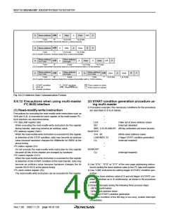
✽ When transmitting control data of more than 1 byte, repeat step ✽.
2
2
✽ Set “D016” in the I C status register (address 00F816). After this, if
AD0 and AAS of the I C status register (address 00F816) are set
ACK is not returned or transmission ends, a STOP condition will
be generated.
to “0” and no interrupt request signal occurs.
2
✽ Set dummy data in the I C data shift register (address 00F616).
✽ When receiving control data of more than 1 byte, repeat step ✽.
✽ When a STOP condition is detected, the communication ends.
Rev.1.00 2003.11.25 page 39 of 128

 RENESAS [ RENESAS TECHNOLOGY CORP ]