M37161M8/MA/MF-XXXSP/FP,M37161EFSP/FP
2
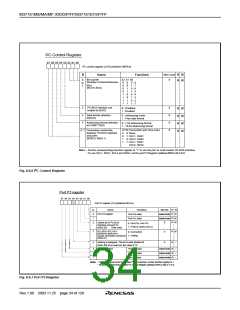
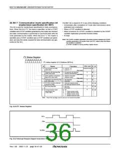
8.6.5 I C Status Register
(5) Bit 4: I2C-BUS interface interrupt request bit (PIN)
This bit generates an interrupt request signal. Each time 1-byte data
is transmitted, the state of the PIN bit changes from “1” to “0.” At the
same time, an interrupt request signal is sent to the CPU. The PIN bit
is set to “0” in synchronization with a falling edge of the last clock
(including the ACK clock) of an internal clock and an interrupt re-
quest signal occurs in synchronization with a falling edge of the PIN
bit. When the PIN bit is “0,” the SCL is kept in the “0” state and clock
generation is disabled. Figure 8.6.9 shows an interrupt request sig-
nal generating timing chart.
2
2
The I C status register (address 00F816) controls the I C-BUS inter-
face status. The low-order 4 bits are read-only bits and the high-
order 4 bits can be read out and written to.
(1) Bit 0: last receive bit (LRB)
This bit stores the last bit value of received data and can also be
used for ACK receive confirmation. If ACK is returned when an ACK
clock occurs, the LRB bit is set to “0.” If ACK is not returned, this bit is
set to “1.” Except in the ACK mode, the last bit value of received data
is input. The state of this bit is changed from “1” to “0” by executing a
The PIN bit is set to “1” in any one of the following conditions.
2
2
write instruction to the I C data shift register (address 00F616).
• Executing a write instruction to the I C data shift register (address
00F616).
(2) Bit 1: general call detecting flag (AD0)
• When the ESO bit is “0”
✽
This bit is set to “1” when a general call whose address data is all
• At reset
“0” is received in the slave mode. By a general call of the master
device, every slave device receives control data after the general
call. The AD0 bit is set to “0” by detecting the STOP condition or
START condition.
The conditions in which the PIN bit is set to “0” are shown below:
• Immediately after completion of 1-byte data transmission (includ-
ing when arbitration lost is detected)
• Immediately after completion of 1-byte data reception
• In the slave reception mode, with ALS = “0” and immediately after
completion of slave address or general call address reception
• In the slave reception mode, with ALS = “1” and immediately after
completion of address data reception
✽General call: The master transmits the general call address “0016”
to all slaves.
(3) Bit 2: slave address comparison flag (AAS)
This flag indicates a comparison result of address data.
(6) Bit 5: bus busy flag (BB)
✽ In the slave receive mode, when the 7-bit addressing format is
selected, this bit is set to “1” in either of the following conditions.
• The address data immediately after occurrence of a START con-
dition matches the slave address stored in the high-order 7 bits
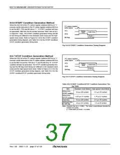
This bit indicates the status of the bus system. When this bit is set to
“0,” this bus system is not busy and a START condition can be gen-
erated. When this bit is set to “1,” this bus system is busy and the
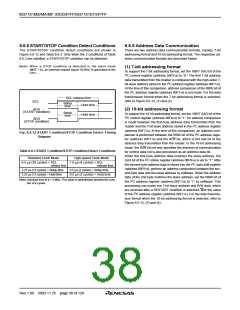
occurrence of a START condition is disabled by the START condition
duplication prevention function (See note).
2
of the I C address register (address 00F716).
• A general call is received.
This flag can be written by software only in the master transmission
mode. In the other modes, this bit is set to “1” by detecting a START
condition and set to “0” by detecting a STOP condition. When the
✽ In the slave reception mode, when the 10-bit addressing format is
selected, this bit is set to “1” in the following condition.
2
2
• When the address data is compared with the I C address regis-
ESO bit of the I C control register (address 00F916) is “0” at reset,
ter (8 bits consisting of slave address and RBW), the first bytes
match.
the BB flag is kept in the “0” state.
✽ The state of this bit is changed from “1” to “0” by executing a write
(7) Bit 6: communication mode specification bit
(transfer direction specification bit: TRX)
2
instruction to the I C data shift register (address 00F616).
This bit decides the direction of transfer for data communication. When
this bit is “0,” the reception mode is selected and the data of a trans-
mitting device is received. When the bit is “1,” the transmission mode
is selected and address data and control data are output into the
SDA in synchronization with the clock generated on the SCL.
✽
(4) Bit 3: arbitration lost detecting flag (AL)
In the master transmission mode, when a device other than the mi-
crocomputer sets the SDA to “L,” arbitration is judged to have been
lost, so that this bit is set to “1.” At the same time, the TRX bit is set to
“0,” so that immediately after transmission of the byte whose arbitra-
tion was lost is completed, the MST bit is set to “0.” When arbitration
is lost during slave address transmission, the TRX bit is set to “0” and
the reception mode is set. Consequently, it becomes possible to re-
ceive and recognize its own slave address transmitted by another
master device.
2
When the ALS bit of the I C control register (address 00F916) is “0” in
the slave reception mode, the TRX bit is set to “1” (transmit) if the
___
least significant bit (R/W bit) of the address data transmitted by the
___
master is “1.” When the ALS bit is “0” and the R/W bit is “0,” the TRX
bit is cleared to “0” (receive).
The TRX bit is cleared to “0” in one of the following conditions.
• When arbitration lost is detected.
✽Arbitration lost: The status in which communication as a master is
• When a STOP condition is detected.
disabled.
• When occurence of a START condition is disabled by the START
condition duplication prevention function (Note).
• When MST = “0” and a START condition is detected.
• When MST = “0” and ACK non-return is detected.
• At reset
Rev.1.00 2003.11.25 page 35 of 128

 RENESAS [ RENESAS TECHNOLOGY CORP ]