M37161M8/MA/MF-XXXSP/FP,M37161EFSP/FP
(8) Bit 7: Communication mode specification bit
(master/slave specification bit: MST)
The MST bit is cleared to “0” in any of the following conditions.
• Immediately after completion of 1-byte data transmission when
arbitration lost is detected
This bit is used for master/slave specification in data communica-
tions. When this bit is “0,” the slave is specified, so that a START
condition and a STOP condition generated by the master are received,
and data communication is performed in synchronization with the
clock generated by the master. When this bit is “1,” the master is
specified and a START condition and a STOP condition are gener-
ated, and also the clocks required for data communication are gen-
erated on the SCL.
• When a STOP condition is detected.
• When occurence of a START condition is disabled by the START
condition duplication prevention function (Note).
• At reset
Note:The START condition duplication prevention function disables the START
condition generation, bit counter reset, and SCL output, when the follow-
ing condition is satisfied:
a START condition is set by another master device.
2
I
r
b7
b3 b2 b1 b0
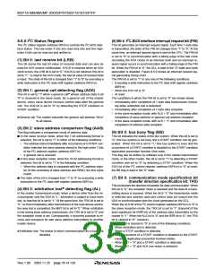
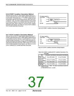
I2C status register (S1) [Address 00F816]
After reset
B
Name
Functions
W
R
0
Last receive bit (LRB)
(See note)
0 : Last bit = “0 ”
1 : Last bit = “1 ”
Indeterminate
R —
R —
R —
(See note)
1
2
General call detecting flag
(AD0) (See note)
0 : No general call detected
1 : General call detected
0
0
(See note)
Slave address comparison
flag (AAS) (See note)
0 : Address mismatch
1 : Address match
(See note)
(See note)
3
4
5
Arbitration lost detecting flag 0 : Not detected
(AL) (See note)
0
1
0
0
R —
R W
R W
R W
1 : Detected
I2C-BUS interface interrupt
request bit (PIN)
0 : Interrupt request issued
1 : No interrupt request issued
Bus busy flag (BB)
0 : Bus free
1 : Bus busy
6, 7 Communication mode
specification bits
b7 b6
0
0
1
1
0 : Slave recieve mode
1 : Slave transmit mode
0 : Master recieve mode
1 : Master transmit mode
(TRX, MST)
Note : These bits and flags can be read out, but cannnot be written.
2
Fig. 8.6.8 I C Status Register
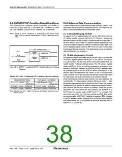
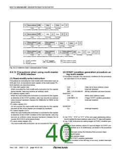
SCL
PIN
IICIRQ
Fig. 8.6.9 Interrupt Request Signal Generation Timing
Rev.1.00 2003.11.25 page 36 of 128

 RENESAS [ RENESAS TECHNOLOGY CORP ]