M37161M8/MA/MF-XXXSP/FP,M37161EFSP/FP
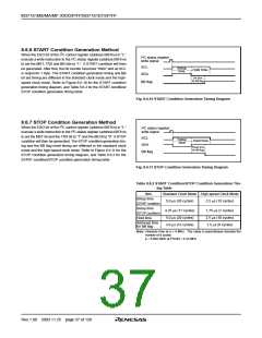
8.6.6 START Condition Generation Method
2
When the ESO bit of the I C control register (address 00F916) is “1,”
I2C status register
write signal
2
execute a write instruction to the I C status register (address 00F816)
to set the MST, TRX and BB bits to “1.” A START condition will then
be generated. After that, the bit counter becomes “0002” and an SCL
is output for 1 byte. The START condition generation timing and BB
bit set timing are different in the standard clock mode and the high-
speed clock mode. Refer to Figure 8.6.10 for the START condition
generation timing diagram, and Table 8.6.2 for the START condition/
STOP condition generation timing table.
SCL
SDA
Setup
time
Hold time
Set time
for BB flag
BB flag
Fig. 8.6.10 START Condition Generation Timing Diagram
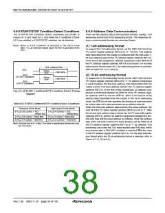
8.6.7 STOP Condition Generation Method
2
When the ESO bit of the I C control register (address 00F916) is “1,”
I2C status register
write signal
2
execute a write instruction to the I C status register (address 00F816)
to set the MST bit and the TRX bit to “1” and the BB bit to “0”. A STOP
condition will then be generated. The STOP condition generation tim-
ing and the BB flag reset timing are different in the standard clock
mode and the high-speed clock mode. Refer to Figure 8.6.11 for the
STOP condition generation timing diagram, and Table 8.6.2 for the
START condition/STOP condition generation timing table.
SCL
Setup
time
Hold time
SDA
Reset time
for BB flag
BB flag
Fig. 8.6.11 STOP Condition Generation Timing Diagram
Table 8.6.2 START Condition/STOP Condition Generation Tim-
ing Table
Item
Standard Clock Mode High-speed Clock Mode
Setup time
(START condition)
Setup time
(STOP condition)
Hold time
5.0 µs (20 cycles)
2.5 µs (10 cycles)
4.25 µs (17 cycles)
5.0 µs (20 cycles)
3.0 µs (12 cycles)
1.75 µs (7 cycles)
2.5 µs (10 cycles)
1.5 µs (6 cycles)
Set/reset time
for BB flag
Note: Absolute time at φ = 4 MHz. The value in parentheses denotes the
number of φ cycles.
φ = 8.86/2 MHz at FSCIN = 4.43 MHz
Rev.1.00 2003.11.25 page 37 of 128

 RENESAS [ RENESAS TECHNOLOGY CORP ]